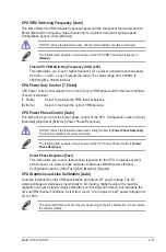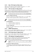
CPU VRM Switching Frequency [Auto]
This item affects the VRM transient response speed and the component thermal production.
Select [Manual] to configure a higher frequency for a quicker transient response speed.
Configuration options: [Auto] [Manual]
DO NOT remove the thermal module. The thermal conditions should be monitored.
The following item appears only when you set the CPU VRM Switching Frequency to
[Manual]
.
Fixed CPU VRM Switching Frequency (KHz) [250]
This item allows you to set a higher frequency for a quicker transient response speed.
Use the <+> and <‑> keys to adjust the value. The values range from 200KHz to
350KHz with a 50KHz interval.
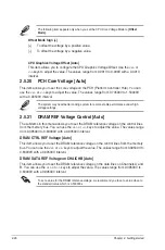
CPU Power Duty Control [T.Probe]
CPU Power Duty Control adjusts the current of every VRM phase and the thermal conditions
of every component.
[T. Probe]
Select to maintain the VRM thermal balance.
[Extreme]
Select to maintain the current VRM balance.
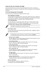
CPU Power Phase Control [Auto]
This item allows you to set the power phase control of the CPU. Configuration options: [Auto]
[Standard] [Optimized] [Extreme] [Power Phase Response]
DO NOT remove the thermal module when setting this item to
[Power Phase Response]
.
The thermal conditions should be monitored.
The following item appears only when you set the CPU Power Phase Control to
[Power
Phase Response]
.
Power Phase Response [Fast]
This item allows you to set a faster phase response for the CPU to increase system
performance or to slower phase response to decrease DRAM power efficiency.
Configuration options: [Ultra Fast] [Fast] [Medium] [Regular]
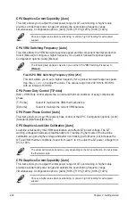
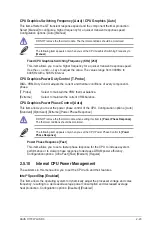
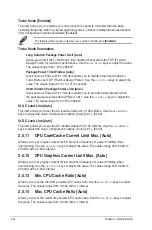
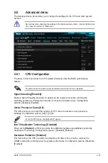
CPU Graphics Load-Line Calibration [Auto]
Load‑line is defined by Intel VRM specification and affects GT power voltage. The GT
working voltage will decrease proportionally to GT loading. Higher levels of the load‑line
calibration can get a higher voltage and better overclocking performance, but increases the
GT and VRM thermal conditions. Select from level 1 to 8 to adjust the GT power voltage from
0% to 100%.
The actual performance boost may vary depending on the GT specification. Do not remove
the thermal module.
ASUS H170I-PLUS D3
2-21
Summary of Contents for H170I-PLUS D3
Page 1: ...Motherboard H170I PLUS D3 ...
Page 10: ...x ...
Page 15: ...ASUS H170I PLUS D3 1 5 Top of CPU Bottom of CPU Bottom of CPU Top of CPU ...
Page 19: ...ASUS H170I PLUS D3 1 9 2 3 To remove a DIMM B A ...
Page 34: ...1 24 Chapter 1 Product introduction ...

