background image

H81M-V3

Motherboard

Summary of Contents for H81M-V3

Page 1: ...H81M V3 Motherboard ...

Page 2: ...ctive companies and are used only for identification or explanation and to the owners benefit without intent to infringe Offer to Provide Source Code of Certain Software This product contains copyrighted software that is licensed under the General Public License GPL under the Lesser General Public License Version LGPL and or other Free Open Source Software Licenses Such software in this product is...

Page 3: ...4 1 4 System memory 1 7 1 5 Expansion slots 1 10 1 6 Headers 1 12 1 7 Connectors 1 13 1 8 Software support 1 23 Chapter 2 BIOS information 2 1 Managing and updating your BIOS 2 1 2 2 BIOS setup program 2 5 2 3 My Favorites 2 9 2 4 Main menu 2 10 2 5 Ai Tweaker menu 2 11 2 6 Advanced menu 2 12 2 7 Monitor menu 2 12 2 8 Boot menu 2 13 2 9 Tools menu 2 14 2 10 Exit menu 2 14 Appendices Notices 15 ASU...

Page 4: ...rd and adding components carefully read all the user guides that came with the package Before using the product ensure all cables are correctly connected and the power cables are not damaged If you detect any damage contact your dealer immediately To avoid short circuits keep paper clips screws and staples away from connectors slots sockets and circuitry Avoid dust humidity and temperature extreme...

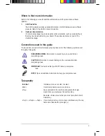
Page 5: ... properly take note of the following symbols used throughout this guide DANGER WARNING Information to prevent injury to yourself when completing a task CAUTION Information to prevent damage to the components when completing a task IMPORTANT Instructions that you MUST follow to complete a task NOTE Tips and additional information to help you complete a task Typography Bold text Indicates a menu or ...

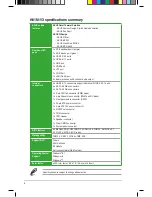
Page 6: ...al characteristics of individual CPUs Please refer to the Memory QVL for details Due to Intel chipset limitation DDR3 1600 MHz and higher memory modules on XMP mode will run at the maximum transfer rate of DDR3 1600 MHz Refer to www asus com for the latest Memory QVL Qualified Vendors List When you install a total memory of 4GB capacity or more Windows 32 bit operating system may only recognize le...

Page 7: ...ts at back panel 8 x USB2 0 1 1 ports 6 ports at midboard 2 ports at back panel ASUS unique features ASUS 5X Protection ASUS motherboards safeguard your PC with 5X Protection DIGI VRM DRAM Fuse ESD Guards High Quality 5K Hour Solid Capacitors and Stainless Steel Back ASUS Digital Power Design Digital Power Control Digital Power Design for the CPU ASUS 4 Phase Power Design ASUS CPU power utility AS...

Page 8: ...rs support additional 6 USB 2 0 1 1 ports 2 x SATA 6 0 Gb s connectors 2 x SATA 3 0 Gb s connectors 1 x 4 pin CPU fan connector PWM mode 1 x 4 pin Chassis fan connector PWM and DC mode 1 x Front panel audio connector AAFP 1 x 24 pin ATX power connector 1 x 4 pin ATX 12V power connector 1 x S PDIF out connector 1 x COM connector 1 x TPM Header 1 x Speaker connector 1 x Clear CMOS connector 1 x Syst...

Page 9: ...as the power supply case to avoid damaging them due to static electricity Hold components by the edges to avoid touching the ICs on them Whenever you uninstall any component place it on a grounded antistatic pad or in the bag that came with the component Before you install or remove any component ensure that the ATX power supply is switched off or the power cord is detached from the power supply F...

Page 10: ...board components 1 2 1 Placement direction When installing the motherboard place it into the chassis in the correct orientation The edge with external ports goes to the rear part of the chassis as indicated in the image 1 2 2 Screw holes Place six screws into the holes indicated by circles to secure the motherboard to the chassis Do not overtighten the screws Doing so can damage the motherboard Pl...

Page 11: ...l port connector 10 1 pin COM2 1 19 2 ATX power connectors 24 pin ATXPWR 4 pin ATX12V 1 15 3 CPU and chassis fan connectors 4 pin CPU_FAN 4 pin CHA_FAN 1 18 4 Intel LGA1150 CPU socket 1 4 5 DDR3 DIMM slots 1 7 6 Intel H81 Serial ATA 6 0Gb s connector 7 pin SATA6G_1 2 1 17 7 Intel H81 Serial ATA 3 0Gb s connector 7 pin SATA3G_1 2 1 17 8 System panel connector 10 1 pin F_PANEL 1 21 9 Speaker connect...

Page 12: ... cap after installing the motherboard ASUS will process Return Merchandise Authorization RMA requests only if the motherboard comes with the cap on the LGA1150 socket The product warranty does not cover damage to the socket contacts resulting from incorrect CPU installation removal or misplacement loss incorrect removal of the PnP cap 1 3 Central Processing Unit CPU This motherboard comes with a s...

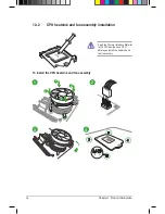
Page 13: ...1 3 1 Installing the CPU 1 2 3 5 4 A B A B C ASUS H81M V3 1 5 ...

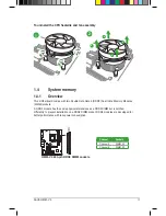
Page 14: ...embly installation Apply the Thermal Interface Material to the CPU heatsink and CPU before you install the heatsink and fan if necessary 3 4 To install the CPU heatsink and fan assembly 2 B A A B 1 1 6 Chapter 1 Product introduction ...

Page 15: ...ory Modules DIMM sockets A DDR3 module has the same physical dimensions as a DDR2 DIMM but is notched differently to prevent installation on a DDR2 DIMM socket DDR3 modules are developed for better performance with less power consumption Channel Sockets Channel A DIMM_A1 Channel B DIMM_B1 H81M V3 H81M V3 240 pin DDR3 DIMM sockets DIMM_A1 DIMM_B1 ASUS H81M V3 1 7 ...

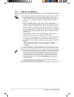
Page 16: ...dules on XMP mode will run at the maximum transfer rate of DDR3 1600 MHz Due to the memory address limitation on 32 bit Windows OS when you install 4GB or more memory on the motherboard the actual usable memory for the OS can be about 3GB or less For effective use of memory we recommend that you do any of the following Use a maximum of 3GB system memory if you are using a 32 bit Windows OS Install...

Page 17: ...1 4 3 Installing a DIMM To install a DIMM 1 2 3 To remove a DIMM ASUS H81M V3 1 9 ...

Page 18: ...e the card to the chassis with the screw you removed earlier 6 Replace the system cover 1 5 2 Configuring an expansion card After installing the expansion card configure it by adjusting the software settings 1 Turn on the system and change the necessary BIOS settings if any See Chapter 2 for information on BIOS setup 2 Assign an IRQ to the card 3 Install the software drivers for the expansion card...

Page 19: ...B C D E F G H PCIEx16 shared PCIEx1_1 shared Realtek 8111G controller shared PCI 1 shared PCI 2 shared USB2 0 controller 1 shared USB2 0 controller 2 shared HD audio shared SATA controller 1 shared SATA controller 2 shared ASUS H81M V3 1 11 ...

Page 20: ...he system hangs due to overclocking For system failure due to overclocking use the CPU Parameter Recall C P R feature Shut down and reboot the system then the BIOS automatically resets parameter settings to default values 1 6 Headers Clear RTC RAM 2 pin CLRTC This header allows you to clear the Real Time Clock RTC RAM in CMOS You can clear the CMOS memory of date time and system setup parameters b...

Page 21: ...r USB 3 0 driver installation USB 3 0 devices can only be used for data storage We strongly recommend that you connect USB 3 0 devices to USB 3 0 ports for faster and better performance from your USB 3 0 devices 4 LAN RJ 45 port This port allows Gigabit connection to a Local Area Network LAN through a network hub LAN port LED indications LAN port Speed LED Activity Link LED Activity Link LED Speed...

Page 22: ...S 2 keyboard Audio 2 1 4 1 5 1 or 7 1 channel configuration Port Headset 2 1 channel 4 1 channel 5 1 channel 7 1 channel Light Blue Rear panel Line In Rear Speaker Out Rear Speaker Out Rear Speaker Out Lime Rear panel Line Out Front Speaker Out Front Speaker Out Front Speaker Out Pink Rear panel Mic In Mic In Bass Center Bass Center Lime Front panel Side Speaker Out 5 Line In port light blue This ...

Page 23: ...m power supply requirement for your system refer to the Recommended Power Supply Wattage Calculator at http support asus com PowerSupplyCalculator PSCalculator aspx SLanguage en us for details 1 7 2 Internal connectors 1 ATX power connectors 24 pin EATXPWR 4 pin ATX12V These connectors are for ATX power supply plugs The power supply plugs are designed to fit these connectors in only one orientatio...

Page 24: ...ector to avail of the motherboard s high definition audio capability If you want to connect a high definition front panel audio module to this connector set the Front Panel Type item in the BIOS setup to HD If you want to connect an AC 97 front panel audio module to this connector set the item to AC97 By default this connector is set to HD See section 2 6 7 Onboard Devices Configuration for detail...

Page 25: ...3G_1 2 This connector connects to Serial ATA 3 0 Gb s hard disk drives via Serial ATA 3 0 Gb s signal cables When using hot plug and NCQ set the SATA Mode Selection item in the BIOS to AHCI SATA6G_1 GND RSATA_RXP1 RSATA_RXN1 GND RSATA_TXN1 RSATA_TXP1 GND SATA6G_2 GND RSATA_RXP2 RSATA_RXN2 GND RSATA_TXN2 RSATA_TXP2 GND H81M V3 H81M V3 SATA 6 0Gb s connectors H81M V3 H81M V3 SATA 3 0Gb s connectors ...

Page 26: ...fan connectors Ensure that the CPU fan cable is securely installed on the CPU fan connector The CPU_FAN connector supports the CPU fan of maximum 1A 12 W fan power Both 3 pin and 4 pin chassis fans support the ASUS Fan Xpert feature The chassis fan connector supports DC and PWM modes To set the chassis fan to DC or PWM go to Advanced Mode Monitor Chassis Fan Q Fan Control item in BIOS CHA_FAN DC m...

Page 27: ... system chassis The COM module is purchased separately 8 Speaker connector 4 pin SPEAKER The 4 pin connector is for the chassis mounted system warning speaker The speaker allows you hear system beeps and warnings H81M V3 H81M V3 Serial port COM2 connector PIN 1 COM2 DCD TXD GND RTS RI RXD DTR DSR CTS H81M V3 5V GND GND Speaker Out SPEAKER PIN 1 H81M V3 Speaker Out connector ASUS H81M V3 1 19 ...

Page 28: ...0 specifications and supports up to 480Mbps connection speed Never connect a 1394 cable to the USB connectors Doing so will damage the motherboard The USB 2 0 module is purchased separately H81M V3 H81M V3 USB2 0 connectors PIN 1 USB 5V USB_P11 USB_P11 GND NC USB 5V USB_P12 USB_P12 GND USB1112 USB910 PIN 1 USB 5V USB_P9 USB_P9 GND NC USB 5V USB_P10 USB_P10 GND USB56 PIN 1 USB 5V USB_P5 USB_P5 GND ...

Page 29: ...HDD_LED This 2 pin connector is for the HDD Activity LED Connect the HDD Activity LED cable to this connector The HDD LED lights up or flashes when data is read from or written to the HDD ATX power button soft off button 2 pin PWR_BTN This connector is for the system power button Reset button 2 pin RESET This 2 pin connector is for the chassis mounted reset button for system reboot without turning...

Page 30: ...s connector The chassis intrusion sensor or switch sends a high level signal to this connector when a chassis component is removed or replaced The signal is then generated as a chassis intrusion event By default the pin labeled Chassis Signal and Ground are shorted with a jumper cap Remove the jumper caps only when you intend to use the chassis intrusion detection feature H81M V3 SPDIF_OUT 5V SPDI...

Page 31: ... package contains the drivers software applications and utilities that you can install to avail all motherboard features The contents of the Support DVD are subject to change at any time without notice Visit the ASUS website at www asus com for updates To run the Support DVD Place the Support DVD into the optical drive If Autorun is enabled in your computer the DVD automatically displays the Speci...

Page 32: ...1 24 Chapter 1 Product introduction ...

Page 33: ...main menu bar EZ Update requires an Internet connection either through a network or an ISP Internet Service Provider 2 1 2 ASUS EZ Flash 2 The ASUS EZ Flash 2 feature allows you to update the BIOS without using an OS based utility Before you start using this utility download the latest BIOS file from the ASUS website at www asus com To update the BIOS using EZ Flash 2 1 Insert the USB flash disk t...

Page 34: ...r a USB flash drive that contains the updated BIOS file Before using this utility rename the BIOS file in the removable device into H81MV3 CAP The BIOS file in the support DVD may not be the latest version Download the latest BIOS file from the ASUS website at www asus com Recovering the BIOS To recover the BIOS 1 Turn on the system 2 Insert the support DVD to the optical drive or the USB flash dr...

Page 35: ...lash drive in FAT32 16 format and single partition 2 Download the latest BIOS file and BIOS Updater from the ASUS website at http support asus com and save them on the USB flash drive NTFS is not supported under DOS environment Do not save the BIOS file and BIOS Updater to a hard disk drive or USB flash drive in NTFS format 3 Turn off the computer and disconnect all SATA hard disk drives optional ...

Page 36: ... between screen fields and use the Up Down Home End keys to select the BIOS file and press Enter BIOS Updater checks the selected BIOS file and prompts you to confirm BIOS update ASUSTek BIOS Updater for DOS V1 30 BOARD H81M V3 VER 0316 DATE 04 11 2014 H81MV3 CAP 8390656 2014 04 11 17 30 48 A 4 Select Yes and press Enter When BIOS update is done press ESC to exit BIOS Updater Restart your computer...

Page 37: ...n keys and brief online help to guide you in using the BIOS Setup program Entering BIOS Setup at startup To enter BIOS Setup at startup Press Delete during the Power On Self Test POST If you do not press Delete POST continues with its routines Entering BIOS Setup after POST To enter BIOS Setup after POST Press Ctrl Alt Del simultaneously Press the reset button on the system chassis Press the power...

Page 38: ...ails If the system fails to boot after changing any BIOS setting try to clear the CMOS and reset the motherboard to the default value See section 1 6 Jumpers for information on how to erase the RTC RAM BIOS menu screen The BIOS setup program can be used under two modes EZ Mode and Advanced Mode You can change modes from the Exit menu or from the Exit Advanced Mode button in the EZ Mode Advanced Mo...

Page 39: ... changes saves the changes and resets the system or enters the Advanced Mode Selects the display language of the BIOS setup program Displays the CPU temperature CPU voltage output DRAM information and CPU chassis fan speed Power Saving mode Normal mode Loads optimized default Displays the system properties of the selected mode on the right hand side Selects the Advanced mode functions Displays the...

Page 40: ... Favorites For saving the frequently used system settings and configuration Main For changing the basic system configuration Ai Tweaker For changing the overclocking settings Advanced For changing the advanced system settings Monitor For displaying the system temperature power status and changing the fan settings Boot For changing the system boot configuration Tool For configuring options for spec...

Page 41: ... F4 on your keyboard or right click on your mouse to add the item to My Favorites page You cannot add the following items to My Favorites Items with submenu options User configurable items such as language and boot device order Configuration items such as Memory SPD Information system time and date 2 3 My Favorites MyFavorites is your personal space where you can easily save and access your favori...

Page 42: ...ation and allows you to set the system date time language and security settings If you have forgotten your BIOS password erase the CMOS Real Time Clock RTC RAM to clear the BIOS password See section 1 6 Jumpers for information on how to erase the RTC RAM The Administrator or User Password items on top of the screen show the default Not Installed After you set a password these items show Installed ...

Page 43: ...ng related items Be cautious when changing the settings of the Ai Tweaker menu items Incorrect field values can cause the system to malfunction The configuration options for this section vary depending on the CPU and DIMM model you installed on the motherboard Scroll down to display the other items ...

Page 44: ...the settings for the CPU and other system devices Be cautious when changing the settings of the Advanced menu items Incorrect field values can cause the system to malfunction 2 7 Monitor menu The Monitor menu displays the system temperature power status and allows you to change the fan settings ...

Page 45: ...ASUS H81M V3 2 13 2 8 Boot menu The Boot menu items allow you to change the system boot options Scroll down to display the other items ...

Page 46: ...igure options for special functions Select an item then press Enter to display the submenu 2 10 Exit menu The Exit menu items allow you to load the optimal default values for the BIOS items and save or discard your changes to the BIOS items You can access the EZ Mode from the Exit menu ...

Page 47: ...t to which the receiver is connected Consult the dealer or an experienced radio TV technician for help The use of shielded cables for connection of the monitor to the graphics card is required to assure compliance with FCC regulations Changes or modifications to this unit not expressly approved by the party responsible for compliance could void the user s authority to operate this equipment IC Can...

Page 48: ... indicates that the battery should not be placed in municipal waste ASUS Recycling Takeback Services ASUS recycling and takeback programs come from our commitment to the highest standards for protecting our environment We believe in providing solutions for you to be able to responsibly recycle our products batteries other components as well as the packaging materials Please go to http csr asus com...

Page 49: ...ddress 800 Corporate Way Fremont CA 94539 USA Telephone 1 510 739 3777 Fax 1 510 608 4555 Web site http www asus com us Technical Support Support fax 1 812 284 0883 General support 1 812 282 2787 Online support http www service asus com ASUS COMPUTER GmbH Germany and Austria Address Harkort Str 21 23 D 40880 Ratingen Germany Fax 49 2102 959931 Web site http www asus com de Online contact http eu r...

Page 50: ... 1 2010 09 EN 302 326 2 V1 2 2 2007 06 EN 302 326 3 V1 3 1 2007 09 EN 301 357 2 V1 4 1 2008 11 EN 302 291 1 V1 1 1 2005 07 EN 302 291 2 V1 1 1 2005 07 2006 95 EC LVD Directive EN 60950 1 A12 2011 EN 60065 2002 A12 2011 2009 125 EC ErP Directive Regulation EC No 1275 2008 Regulation EC No 642 2009 Regulation EC No 278 2009 Regulation EC No 617 2013 2011 65 EU RoHS Directive Ver 130816 CE marking De...

Reviews: