


ASUS P3W User’s Manual
77
4. BIOS SETUP
4. BIOS SETUP
Plug & Play O/S [No]
This field allows you to use a Plug-and-Play (PnP) operating system to con-
figure the PCI bus slots instead of using the BIOS. When [Yes] is selected,
interrupts may be reassigned by the OS. When a non-PnP OS is installed or
you want to prevent reassigning of interrupt settings, select the default set-
ting of [No]. Configuration options: [No] [Yes]
Boot Virus Detection [Enabled]
Configuration options: [Disabled] [Enabled]
Quick Power On Self Test [Enabled]
Configuration options: [Disabled] [Enabled]
Boot Up Floppy Seek [Enabled]
Configuration options: [Disabled] [Enabled]
Boot Up NumLock Status [On]
Configuration options: [Off] [On]
Full Screen Logo [Enabled]
Configuration options: [Disabled] [Enabled]
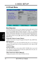
Boot Menu


