background image

iPBX30 User Manual 

Chapter 12

121

• 

ITSP Operator

  Select one extension number as the ITSP inbound call reception 

operator. The extension must be predefined in the “Extension” 

page. All incoming calls from ITSP SIP will be forwarded to this 

extension.

• 

User Name/Password

  The ITSP will give you an account name and password for 

device registration authentication. Enter the account name 

here, followed by password and authentication method.

• 

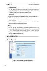
Authentication

  The  iPBX30  supports  MD5  authentication  method  while 

registering to ITSP. Normally the SIP server registration is 

protected for preventing unauthorized user login.

12.2.3 

Prefix Routing

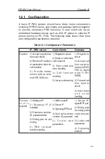
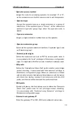
“Prefix routing” enables user to define a prefix code mapping for 

routing calls to a specified destination.
The destination could be a gateway or ITSP service server. Prefix 

routing must work with “Gateway” or “ITSP” setting.

Figure 12.7  Prefix Routing page

Summary of Contents for iPBX30

Page 1: ...iPBX30 User Manual E2883 December 2006 ...

Page 2: ...atures 3 2 3 Software Features 4 2 3 1 NAT Features 4 2 3 2 Firewall Features 5 2 3 2 1 Stateful Packet Inspection 5 2 3 2 2 Packet Filtering ACL Access Control List 5 2 3 2 3 Defense against DoS Attacks 6 2 3 2 4 Application Level Gateway ALG 7 2 3 2 5 Log 7 2 4 Finding Your Way Around 8 2 4 1 Front Panel 8 2 4 2 Rear Panel 9 2 4 3 Bottom View 10 2 5 Placement Options 10 2 5 1 Desktop Placement 1...

Page 3: ... ME PC 16 3 2 5 Windows NT 4 0 workstation 17 3 2 6 Assigning static IP addresses to your PC 18 3 3 Part 3 Quick Configuration of the iPBX30 19 3 3 1 Setting Up the iPBX30 19 3 3 2 Testing Your Setup 21 3 3 3 Default Router Settings 22 4 Using the Web UI Management 23 4 1 Log into the Web UI Management 23 4 2 Functional Layout 24 4 2 1 Menu Navigation 25 4 2 2 Commonly Used Buttons and Icons 25 4 ...

Page 4: ...ation Parameters 37 5 2 5 2 Configuring Static IP for WAN or DMZ 38 5 2 6 PPTP 39 5 2 6 1 WAN PPTP Configuration Parameters 39 5 2 6 2 Configuring PPTP for WAN 41 5 3 WAN Load Balancing and Line Back Up 41 5 3 1 WAN Load Balancing and Line Back Up Configuration Parameters 42 5 3 2 Setting Up WAN Load Balancing 43 5 3 3 Setting Up WAN Line Back Up 44 6 DHCP Server Configuration 45 6 1 DHCP Dynamic ...

Page 5: ...ynamic Routing using RIP Routing Information Protocol 53 7 2 1 RIP Configuration Parameters 53 7 2 2 Configuring RIP 54 7 3 Static Route 55 7 3 1 Static Route Configuration Parameters 55 7 3 2 Adding Static Routes 56 7 3 3 Deleting Static Routes 57 7 3 4 Viewing the Static Routing Table 57 8 Configuring DDNS 58 8 1 DDNS Configuration Parameters 59 8 2 Configuring HTTP DDNS Client 59 9 Configuring ...

Page 6: ...gs 69 9 4 ACL Rule Configuration Parameters 69 9 4 1 ACL Rule Configuration Parameters 69 9 5 Configuring ACL Rules Firewall ACL 73 9 5 1 Add an ACL Rule 74 9 5 2 Modify an ACL Rule 76 9 5 3 Delete an ACL Rule 76 9 5 4 Display ACL Rules 76 9 6 Configuring Self Access ACL Rules Firewall NAT Self Access ACL 76 9 6 1 Add a Self Access Rule 77 9 6 2 Modify a Self Access Rule 78 9 6 3 Delete a Self Acc...

Page 7: ...System Services 94 11 2 Login Password and System Settings 95 11 2 1 Changing Password 95 11 2 2 Configure System Settings 96 11 3 Viewing System Information 96 11 4 Setup Date and Time 97 11 4 1 View the System Date and Time 98 11 5 SNMP Setup 99 11 5 1 SNMP Configuration Parameters 99 11 5 2 Configuring SNMP 99 11 6 Log Setup 100 11 6 1 Setting Up Remote Logging Using a Syslog Server 100 11 6 2 ...

Page 8: ... Dialing Plan 118 12 2 1 General 118 12 2 2 ITSP Server 120 12 2 3 Prefix Routing 121 12 3 Status 122 12 3 1 Extensions Status 122 12 3 2 Channel Status 123 12 3 3 ITSP Registry 123 12 4 Features 124 12 4 1 Voicemail 124 12 4 2 Auto provision for AX 112 128 12 5 Report 129 12 6 Utilities 129 12 6 1 Hot Reload 129 12 6 2 Service Restart 130 12 7 Configuring Examples 130 13 IP Addresses Network Mask...

Page 9: ...ogin Screen 20 Figure 3 3 System Status Page 21 Figure 4 1 Login Screen 24 Figure 4 2 Typical Web UI Management Page 25 Figure 4 3 System Status Page 26 Figure 5 1 Network Setup Configuration LAN Configuration 28 Figure 5 2 Network Setup Configuration Page WAN Configura tion 30 Figure 5 3 WAN PPPoE Configuration 30 Figure 5 4 WAN PPPoE Unnumbered Configuration 33 Figure 5 5 WAN Dynamic IP DHCP cli...

Page 10: ...ber or IP Address 65 Figure 9 3 Firewall General Configuration Page 69 Figure 9 4 ACL Configuration Page 74 Figure 9 5 ACL Configuration Example 75 Figure 9 6 Sample ACL List Table 75 Figure 9 7 Self Access ACL Configuration Page 77 Figure 9 8 Self Access ACL Configuration Example 78 Figure 9 9 Virtual Server Configuration Page 79 Figure 9 10 Virtual Server Deployment Topology 82 Figure 9 11 Virtu...

Page 11: ...re System Configuration Page 104 Figure 11 13 Selecting System Configuration from the File Manager 105 Figure 11 14 System Configuration Restoration Confirmation 105 Figure 11 15 System Reboot Counter Timer 106 Figure 11 16 Firmware Upgrade Page 106 Figure 11 17 Selecting Firmware from the File Manager 107 Figure 11 18 Firmware Upgrade Confirmation 107 Figure 11 19 Firmware Upgrade Progress 107 Fi...

Page 12: ... SIP page 132 Figure 14 1 Using the ping Utility 142 Figure 14 2 Using the nslookup Utility 143 List of Tables Table 2 1 DoS Attacks 6 Table 2 2 Front Panel Label and LEDs 8 Table 2 3 Rear Panel Labels and LEDs 9 Table 3 1 LED Indicators 14 Table 3 2 Default Settings Summary 22 Table 4 1 Description of Commonly Used Buttons and Icons 25 Table 5 1 LAN Configuration Parameters 28 Table 5 2 WAN PPPoE...

Page 13: ...n 67 Table 9 3 ACL Rule Configuration Parameters 70 Table 9 4 Service Configuration Parameters 72 Table 9 5 Virtual Server Configuration Parameters 80 Table 9 6 Port Numbers for Popular Applications 81 Table 9 7 Special Application Configuration Parameters 87 Table 9 8 Port Numbers for Popular Applications 87 Table 10 1 Network Storage Configuration 90 Table 10 2 FTP Sever Configuration 92 Table 1...

Page 14: ...d NAT Network Address Translation functions to provide secure Internet access for your LAN Automatic network address assignment through DHCP Server Services including IP route DNS and DDNS configuration User configurable dual WAN or WAN plus DMZ support USB storage support SIP based IP PBX support allowing up to30 SIP clients registration Support SIP trunking to ITSP and SIP gateway routing IP PBX...

Page 15: ... or acronyms that may be unfamiliar to many readers These terms are also included in the Glossary Warning Provides messages of high importance including messages relating to personal safety or system integrity The iPBX30 is sometimes referred to as the router or the gateway The terms LAN and network are used interchangeably to refer to a group of Ethernet connected computers at one site Sequence o...

Page 16: ...Parts List Your iPBX30 package include these items iPBX30 AC adapter Ethernet cable straight through type 2 2 Hardware Features Your iPBX30 contains these hardware features LAN 4 port Fast Ethernet switch Auto speed negotiation WAN Dual 10 100M Ethernet ports Auto MDI MDIX ...

Page 17: ...ers etc The NAT rules drive the translation mechanism The following types of NAT are supported by iPBX30 NAPT Network Address and Port Translation Also called IP Masquerading or ENAT Enhanced NAT Maps many internal hosts to only one globally valid IP address The mapping usually contains a pool of network ports to be used for translation Every packet is translated with the globally valid IP address...

Page 18: ...d ones This provides a solution which is highly secure and that offers scalability and extensibility 2 3 2 2 Packet Filtering ACL Access Control List ACL rule is one of the basic building blocks for network security Firewall monitors each individual packet decodes the header information of inbound and outbound traffic and then either blocks the packet from passing or allows it to pass based on the...

Page 19: ...all also provides protection from a variety of common Internet attacks such as IP Spoofing Ping of Death Land Attack and Reassembly attacks The type of attack protections provided by the iPBX30 is listed in the table below Table 2 1 DoS Attacks Type of Attack Name of Attacks Re assembly Attacks Bonk Boink Teardrop New Tear Overdrop Opentear Syndrop Jolt IP fragmentation overlap ICMP Attacks Ping o...

Page 20: ...to create policies for numerous applications dynamically at the same time without compromising security intelligence in the form of Application Level Gateways ALG is built to parse packets for applications and open dynamic associations The iPBX30 NAT provides a number of ALGs for popular applications such as FTP and Netmeeting 2 3 2 5 Log Events in the network that could be attempts to affect its ...

Page 21: ...wered off 2 Status Green 3 USB Identifies the USB port LEDs 1 2 Green OFF USB device is not detected ON USB device is detected 4 WAN1 and WAN2 DMZ OFF No link is detected Green ON 100Mbps link is detected Blinking 100Mbps activity is detected Amber ON 10Mbps link is detected Blinking 10Mbps activity is detected 5 LAN Identifies the LAN port LEDs 1 4 OFF No link is detected Green ON 100Mbps link is...

Page 22: ...SL or cable modem or DMZ network The DMZ network must be connected to the port labeled as WAN2 DMZ 8 USB USB Ports connect to USB 1 1 OR 2 0 devices 9 Console Not supported 10 RESET Reset Button 1 Reboot the device 2 Reset the system configuration to factory defaults if pressed for more than 5 seconds 11 POWER Power Input Jack Connect to the supplied AC adapter 2 4 2 Rear Panel The rear panel cont...

Page 23: ...p or right side up 2 5 Placement Options Choose one of the supported placement options for the iPBX30 desktop placement and wall mount 2 5 1 Desktop Placement You may place the iPBX30 on any flat surface The space saving design of iPBX30 occupies only a small area on your desk 2 5 2 Wall Mount Instructions 1 Attach two screws on the wall and with a 150mm distance between the two screws 12 12 150mm...

Page 24: ... orientations rear side up rear side down rear side to the left and rear side to the right Screw Wall mount slot Line up the wall mount slot with both screws Maneuver the router so that both screws are inserted into the wall mount slots and then slowly push the router downward as shown in the figure above Wall mount slot Screw ...

Page 25: ...all office network setup Refer to the subsequent chapters for additional configuration instructions Note To verify that your setup is working properly refer to 3 3 2 Testing Your Setup 3 1 Part 1 Connecting the Hardware This section instructs you on how to connect the device to an ADSL or a cable modem which in turn is connected to a phone jack or a cable outlet the power outlet and your computer ...

Page 26: ...r instructions and the other to the Ethernet switch port labeled 1 4 on the iPBX30 You can use either crossover or straight through Ethernet cables to connect the built in switch and computers hubs or switches as the built in switch allows connections with either type of cables 3 1 3 Step 3 Attaching the AC adapter Attach the AC adapter to the POWER input jack on the back of the device and plug in...

Page 27: ...e device is sending or receiving data to from the Internet 3 2 Part 2 Configuring Your Computers This section provides instructions for configuring the network settings on your computers to work with the iPBX30 3 2 1 Before you begin By default the iPBX30 automatically assigns all required network settings e g IP address DNS server IP address default gateway IP address to your PCs You need only to...

Page 28: ...Also click the radio button labeled Obtain DNS server address automatically 6 Click OK button twice to confirm your changes and close the Control Panel 3 2 3 Windows 2000 PC First check for the IP protocol and if necessary install it 1 In the Windows task bar click the Start button point to Settings and then click Control Panel 2 Double click the Network and Dial up Connections icon 3 In the Netwo...

Page 29: ...col TCP IP and then click Properties button 11 In the Internet Protocol TCP IP Properties dialog box click the radio button labeled Obtain an IP address automatically Also click the radio button labeled Obtain DNS server address automatically 12 Click OK button twice to confirm and save your changes and then close the Control Panel 3 2 4 Windows 95 98 and ME PC 1 In the Windows task bar click the ...

Page 30: ...e name of your network adapter and then click Properties button 9 In the TCP IP Properties dialog box click the radio button labeled Obtain an IP address automatically 10 In the TCP IP Properties dialog box click the Default Gateway tab Enter 192 168 1 1 the default LAN port IP address of the iPBX30 in the New gateway address field and click Add button to add the default gateway entry 11 Click OK ...

Page 31: ... OK button if prompted to restart your computer Next configure the PCs to accept IP addresses assigned by the iPBX30 7 Open the Control Panel window and then double click the Network icon 8 In the Network dialog box click the Protocols tab 9 In the Protocols tab select TCP IP and then click Properties button 10 In the Microsoft TCP IP Properties dialog box click the radio button labeled Obtain an ...

Page 32: ...ic assignment of the IP addresses for the computer DNS server and default gateway click the radio buttons that enable you to enter the information manually Note Your PCs must have IP addresses that place them in the same subnet as the iPBX30 s LAN port If you manually assign IP information to all your LAN PCs you can follow the instructions in Chapter 5 to change the LAN port IP address accordingl...

Page 33: ... check the following items a Check if your PC is configured to accept IP address assignment from the iPBX30 b Set the IP address of your PC to any IP address in the 192 168 1 0 network such as 192 168 1 2 14 Enter your username and password and then click OK to enter the Web UI Management The first time you log into this program use these defaults Default Username admin Default Password admin You ...

Page 34: ...e Internet 3 3 2 Testing Your Setup At this point the iPBX30 should enable any computers on your LAN to use the iPBX30 s ADSL or cable modem connection to access the Internet To test the Internet connection open your web browser and type the URL of any external website such as http www asus com The LED labeled WAN should be blinking rapidly and may appear solid as the device connects to the site Y...

Page 35: ...g any modification or contact your ISP for assistance Before you modifying any settings review Chapter 4 for general information about accessing and using the Web UI Management program We strongly recommend that you contact your ISP prior to changing the default configuration Table 3 2 Default Settings Summary Option Default Setting Explanation Instruction DHCP Dynamic Host Configuration Protocol ...

Page 36: ... access the software you need the following A computer connected to the LAN or WAN port on the iPBX30 as described in the chapter 3 A web browser installed on the computer The program is designed to work best with Microsoft Internet Explorer 6 0 or later You may access the software from any computer connected to the iPBX30 via the LAN or WAN ports However the instructions provided here are for com...

Page 37: ...appears every time you log into the software shown in Figure 3 3 4 2 Functional Layout A typical page in the software consists of several elements banner menu menu navigation tips configuration and on line help You can click on any menu item to expand contract any menu groups or to access a specific configuration page The configuration pane is where you interact with the software to configure the ...

Page 38: ... buttons or icons are used throughout the application The following table describes the function for each button or icon Table 4 1 Description of Commonly Used Bottons and Icons Button Function Stores any changes you have made on the current page Adds the existing configuration to the system e g a static route or a firewall ACL rule and etc Modifies the existing configuration in the system e g a s...

Page 39: ...figuration Overview To view the overall system configuration log into the iPBX30 Web or click the Status menu if you have already logged on The figure below shows sample information available in the System Status page Figure 4 3 System Status Page ...

Page 40: ...ou must assign a unique IP address to each device residing on your LAN The LAN IP address that identifies the iPBX30 as a node on your network must be in the same subnet as the PCs on your LAN The default LAN IP address for the iPBX30 is 192 168 1 1 Definition A network node can be thought of as any interface where a device connects to the network such as the iPBX30 s LAN port and the network inte...

Page 41: ...nd which parts refer specifically to nodes on the network Your device is preconfigured with a default subnet mask of 255 255 255 0 5 1 3 Configuring the LAN IP Address Follow these steps to change the default LAN IP address 1 Click the Router Setup Connection menu to open the Connection configuration page Figure 5 1 Network Setup Configuration LAN Configuration 2 Optional Enter the host name for i...

Page 42: ... or a small network that sits between a trustful internal network such as a corporate private LAN and an untrusted external network such as the Internet Typically the DMZ contains devices accessible to the Internet traffic such as Web servers FTP servers SMTP e mail servers and DNS servers The DMZ contains no corporate confidential information In the event that the DMZ is compromised no other comp...

Page 43: ... Figure 5 2 Network Setup Configuration Page WAN Configuration 5 2 2 PPPoE PPPoE connection is most often used by ADSL service providers Figure 5 3 WAN PPPoE Configuration Connection Mode drop down list Connection Mode drop down list ...

Page 44: ...name provided by your ISP Service name is optional but may be required by some ISPs AC Name Enter the access concentrator name provided by your ISP Access concentrator name is optional but may be required by some ISPs IPAddress If your ISP allows you to always obtain the same IP address for your WAN enter it here Primary Secondary DNS Server IP address of the primary and or secondary DNS are optio...

Page 45: ...n page 2 Select which WAN port WAN1 WAN2 to configure for PPPoE connection mode 3 Select PPPoE from the WAN Connection Mode drop down list 4 Select PPPoE session ID from the PPPoE session ID drop down list Currently two sessions are supported for each WAN port 5 Enter the service name if required by your ISP 6 Optional Enter the service name or AC name or both if required by your ISP 7 Optional If...

Page 46: ...fault value is 1454 10 Enter the appropriate connection settings for Disconnect after Idle min and Connect on Demand 11 Click Apply to save the settings 5 2 3 PPPoE Unnumbered Some of the ADSL service providers may offer PPPoE unnumbered service Choose this connection mode if your ISP provides such service Connection Mode drop down list ...

Page 47: ...aller Enable NAPT Check or uncheck this box to enable NAPT for this connection User Name and Password Enter the username and password you use to log into your ISP Note this is different from the information you used to log into Web UI Management Service Name Enter the service name provided by your ISP Service name is optional but may be required by some ISPs AC Name Enter the access concentrator n...

Page 48: ...e Connecting iPBX30 is trying to connect to your ISP using PPPoE unnumbered connection mode Manual Disconnect Connect Click the Disconnect or Connect button to disconnect or connect using the PPPoE unnumbered connection mode 5 2 3 2 Configuring PPPoE Unnumbered for WAN Follow the instructions below to configure PPPoE unnumbered settings 1 Click the Router Setup Connection menu to open the Network ...

Page 49: ...condary DNS servers are automatically assigned by the DHCP server of your 8 Optional Enter the IP addresses for the primary or secondary DNS servers or both if you want to use your preferred DNS servers otherwise skip this step 9 Optional Change the MTU value if necessary If you do not know what value to enter leave it as is For dynamic IP connection mode the range of MTU is from 546 to 1492 The d...

Page 50: ...or DMZ Static IP Configuration Parameters The table below describes the configuration parameters available for static IP connection mode Table 5 4 WAN Static IP Configuration Parameters Setting Description Link Select a port to configure Available options are WAN1 WAN2 or WAN DMZ Connection Mode Select Static from the connection mode drop down list IPAddress WAN DMZ IP address Please note that WAN...

Page 51: ...nection menu to open the Network Setup configuration page 2 Select which WAN port WAN1 WAN2 or DMZ port to configure for the static connection mode 3 Select Static from the Connection Mode drop down list 4 Enter WAN IP address in the IP Address field This information should be provided by your ISP 5 Enter Subnet Mask for the WAN This information should be provided by your ISP Typically it is 255 2...

Page 52: ... WAN IP is a fixed IP provided by your ISP IPAddress Enter the WAN IP address provided by your ISP Subnet Mask Enter the subnet mask for the WAN IP provided by your ISP Gateway Address Enter the gateway IP address for the WAN provided by your ISP Dynamic DHCP Select this connection mode if your WAN IP address is obtained automatically from your ISP s DHCP server User Name and Password Enter the us...

Page 53: ... no activity time out The SNTP service may interfere with this function if there are activities from the service Status On PPTP connection is active Off No PPTP connection is active Connecting iPBX30 is trying to connect to your ISP using PPTP connection mode Manual Disconnect Connect Click the Disconnect or Connect button to disconnect or connect using the PPTP connection mode Figure 5 7 WAN PPTP...

Page 54: ...ter PPTP server IP address provided by your ISP 8 Optional Change the MTU value if necessary If you do not know what value to enter leave it as is For PPTP connection mode the range of MTU is from 546 to 1460 The default value is 1460 9 Check MPPE box if the packet is to be encrypted with this protocol 10 Enter the appropriate connection settings for Disconnect after Idle min and Connect on Demand...

Page 55: ...obin This option includes the functionality off line backup It is recommended that this option be selected Line Backup select this option if line backup is needed In the existing implementation the primary link is always set to WAN1 and the backup link is always set to WAN2 W A N 1 W A N 2 Bandwidth Enter the ratio of the traffic amount that you want to distribute between the WANs The number shoul...

Page 56: ... t y Check IP Address WAN1 Enter the IP address of the specific network device that the traffic will pass through This field is optional Normally you don t need to provide any IP address here unless you know the traffic must pass a specific network device C o n n e c t i v i t y Check IP Address WAN2 Enter the IP address of the specific network device that the traffic will pass through This field ...

Page 57: ...led please also enter the following a Enter the connectivity check interval b Optional Enter the connectivity check IP address for WAN1 and or WAN2 5 Click Apply to save the settings 5 3 3 Setting Up WAN Line Back Up Follow the instructions below to set up line backup 1 Click the Router Setup Load Balance menu to open the Load Balancing configuration page 2 Select Line Backup in the Load Balance f...

Page 58: ...ose to have the information assigned dynamically then you configured your PCs as DHCP clients that will accept IP addresses assigned from a DCHP server such as the iPBX30 The DHCP server draws from a defined pool of IP addresses and leases them for a specified amount of time to your computers when they request an Internet session It monitors collects and redistributes the addresses as needed On a ...

Page 59: ...ick Advanced DHCP Server menu to open the DHCP Server Configuration page Figure 6 1 DHCP Server Configuration Page 2 Enter the information for the IP Address Pool Begin End Address Subnet Mask Lease Time and Default Gateway IP Address fields others such as Primary Secondary DNS Server IP Address and Primary Secondary WINS Server IP Address are optional However it is recommended that you enter the ...

Page 60: ... DNS Server IP Address The IP address of the Domain Name System server to be used by computers that receive IP addresses from this pool The DNS server translates common Internet names that you type into your web browser into their equivalent numeric IP addresses Typically the server s are located with your ISP However you may enter LAN IP address of the iPBX30 as it will serve as DNS proxy for the...

Page 61: ...e lists any IP addresses leased and the corresponding MAC addresses Figure 6 2 DHCP Lease Table 6 1 5 Fixed DHCP Lease Fixed DHCP lease is used in situations when a fixed DHCP address is desired for a host that gets IP from the DHCP server First you should configure your PCs to accept DHCP information assigned by a DHCP server 6 1 5 1 Access Fixed DHCP Configuration Page Advanced DHCP Server Click...

Page 62: ...Lease Configuration Parameters Field Description Fixed DHCP Lease MAC A hardware ID of the device that needs a fixed IP address from the DHCP server Fixed DHCP Lease IP The IP address leased from the DHCP server It is recommended that this IP address be outside of the DHCP IP pool 3 Click on the Add button to add the new fixed DHCP lease entry 6 1 5 3 Delete a Fixed DHCP Lease To delete a fixed DH...

Page 63: ...encountering heavy traffic ISPs typically provide primary and secondary DNS addresses and may provide additional addresses Your LAN PCs learn these DNS addresses in one of the following ways Statically If your ISP provides you with their DNS server addresses you can assign them to each PC by modifying the PCs IP properties Dynamically from a DHCP Server You can configure the DNS addresses in the D...

Page 64: ...PPoE protocol Using this option provides the advantage that you will not need to reconfigure the PCs or the iPBX30 if the ISP changes their DNS addresses Configured on the iPBX30 You can also specify the ISP s DNS addresses in the WAN configuration page Follow these steps to configure DNS relay 1 Enter LAN IP in the DNS Server IP Address field in DHCP configuration page 2 Configure the LAN PCs to ...

Page 65: ...uters and for the iPBX30 provide the most appropriate path for all your Internet traffic On your LAN computers a default gateway directs all Internet traffic to the LAN port on the iPBX30 Your LAN computers know their default gateway either because you assigned it to them when you modified their TCP IP properties or because you configured them to receive the information dynamically from a server w...

Page 66: ...Configuration Parameters The following table defines the available configuration parameters for static routing configuration Table 7 1 Static Route Configuration Parameters Field Description Interface Select an interface through which the routing information is exchanged Available options are LAN WAN1 WAN2 PPPoE1 PPPoE2 PPPoE3 and PPPoE4 RIP Click the Enable or Disable radio button to enable or di...

Page 67: ...outers exchanging routing information must use the same authentication key Authentication Mode Select RIP authentication mode from the drop down list Two modes are supported Clear Text and MD5 Authentication Key Enter the authentication key shared by all the routers exchanging the routing information 7 2 2 Configuring RIP Follow these instructions to enable or disable RIP 1 In the System Services ...

Page 68: ...iguration parameters for static routing configuration Table 7 2 Static Route Configuration Parameters Field Description Destination Address Specifies the IP address of the destination computer or an entire destination network It can also be specified as all zeros to indicate that this route should be used for all destinations for which no other route is defined this is the route that creates the d...

Page 69: ... the drop down list If AUTO is selected the router will automatically assign an interface to route the packets based on the gateway IP address 7 3 2 Adding Static Routes Figure 7 3 Static Route Configuration Follow these instructions to add a static route to the routing table 1 Click the Advanced Static Route menu to open the Static Route configuration page 2 Enter static routes information such a...

Page 70: ...le 7 3 4 Viewing the Static Routing Table All IP enabled computers and routers maintain a table of IP addresses that are commonly accessed by their users For each of these destination IP addresses the table lists the IP address of the first hop the data should take This table is known as the device s routing table To view the iPBX30 s routing table click the Advanced Static Route menu The Routing ...

Page 71: ...atures Update DNS records addition when an external interface comes up Force DNS update HTTP DDNS Client HTTP DDNS client uses the mechanism provided by the popular DDNS service providers for updating the DNS records dynamically In this case the service provider updates DNS records in the DNS iPBX30 uses HTTP to trigger this update iPBX30 supports HTTP DDNS update with the following service provid...

Page 72: ... Check this box to enable DDNS service otherwise keep the box unchecked D o m a i n Name Enter the registered domain name into this field For example If the host name of your iPBX30 is host1 and the domain name is yourdomain com The fully qualify domain name FQDN is host1 yourdomain com Username Enter the username provided by your DDNS service provider in this field Password Enter the password pro...

Page 73: ... configuration page 3 Select the interface that the DDNS service is to be used 4 Check Enable DDNS checkbox to enable the DDNS service 5 Enter the registered domain name in the Domain Name field 6 Enter the username and password provided by your DDNS service provider 7 Click on Apply button to send a DNS update request to your DDNS service provider Note that DNS update request will also be sent to...

Page 74: ...lude the network or internet protocol it is carrying the direction in which it is traveling for example from the LAN to the Internet or vice versa the IP address of the sending computer the destination IP address and other characteristics of the packet data If the packet matches the criteria established in a rule the packet can either be accepted forwarded towards its destination or denied discard...

Page 75: ...fic by extracting header information from the packet and then either drops or forwards the packet by looking for a match in the ACL rule table based on the header information The ACL rule checking starts from the rule with the smallest rule ID until a match is found or all the ACL rules are examined If no match is found the packet is dropped otherwise the packet is either dropped or forwarded base...

Page 76: ...c originated from the LAN is forwarded to the external network using NAT WARNING It is not necessary to remove the default ACL rule from the ACL rule table It is better to create higher priority ACL rules to override the default rule 9 2 NAT Overview Network Address Translation allows use of a single device such as the iPBX30 to act as an agent between the Internet public network and a local priva...

Page 77: ...mapping contains a pool of network ports to be used for translation Every packet is translated with the globally valid Internet address and the port number is translated with an un used port from the pool of network ports The figure below shows that all the hosts on the local network gain access to the Internet by mapping to only one globally valid IP address and different port numbers from a free...

Page 78: ...User Manual Chapter 9 65 Figure 9 1 NAPT Map Any Internal PCs to a Single Global IP Address Figure 9 2 Reverse NAPT Relayed Incoming Packets to the Internal Host Base on the Protocol Port Number or IP Address ...

Page 79: ...Settings Firewall NAT Settings 9 3 1 Firewall Options The table below lists the firewall options parameters Table 9 1 Firewall Options Parameters Field Description DoS Check Check or uncheck this box to enable or disable DoS check When DoS check is disabled the following functionalities are disabled Stateful packet inspection Skip all DoS attack check Default NAT Log Port Probing Connection attemp...

Page 80: ...ion Field Description I P S o u r c e Route Intruder uses source routing in order to break into the target system IP Spoofing Spoofing is the creation of TCP IP packets using somebody else s IP address IP spoofing is an integral part of many network attacks that do not need to see responses Land Attacker sends out packets to the system with the same source and destination IP address being that of ...

Page 81: ... sequence number of zero and all control bits are set to zero FIN scan A hacker is scanning the target system using a stealth method The goal of the hacker is to find out if they can connect to the system without really connecting using the FIN scanning It attempts to close a non existent connection on the server Either way it is an error but systems sometimes respond with different error results ...

Page 82: ... Firewall General configuration page 2 Check or uncheck individual check box for each type DoS protection 3 Click Apply to save the settings Figure 9 3 Firewall General Configuration Page 9 4 ACL Rule Configuration Parameters 9 4 1 ACL Rule Configuration Parameters The table below describes the configuration parameters firewall inbound outbound and self access ACL rules ...

Page 83: ...rity Other numbers Select other numbers to indicate the priority you wish to assign to the rule Log Check this box to enable loggingfor this ACL rule otherwise keep it unchecked Action Allow Select this button to configure the rule as an allow rule This rule when bound to the Firewall will allow matching packets to pass through Deny Select this button to configure the rule as a deny rule This rule...

Page 84: ...the computers in the local network for outbound traffic IP Address This option allows you to specify an IP address on which this rule will be applied IP Address Specify the appropriate network address Subnet This option allows you to include all the computers that are connected in an IP subnet When this option is selected the following fields become available Field Description Address Enter the ap...

Page 85: ...iguration Parameters Field Description Service Name Enter a distinctive name identifying the new service Protocol Select a protocol type from the drop down list Available options are All TCP UDP ICMP IGMP AH ESP and TCP UDP Port This option allows you to specify the port number s used by the device Use the drop down list to select one of the following options Any Select this option if the service ...

Page 86: ...xceed time exceeded 12 Parameter problem 13 Timestamp request 14 Timestamp reply 15 Info request information request 16 Info reply information reply 17 Addr mask req address mask request 18 Addr mask reply address mask reply 9 5 Configuring ACL Rules Firewall ACL By creating ACL rules in the ACL configuration page you can perform access control allow or deny to both the trusted and un trusted netw...

Page 87: ...if you want to create an ACL to filter traffic originated from LAN and destined to WAN then choose LAN WAN option 3 Select Add New from the ID drop down list 4 Set desired action Allow or Deny from the Action drop down list 5 Select from the Route To drop down list if you intend to direct the traffic to a specific interface Choose AUTO if you want to have the iPBX30 to route the traffic automatica...

Page 88: ...priority of the rule with 1 being the highest Higher priority rules will be examined prior to the lower priority rules by the firewall 9 Click on the Add button to create the new ACL rule The new ACL rule will then be displayed in the inbound access control list table at the bottom half of the Inbound ACL Configuration page The figure below illustrates how to create a rule to deny outbound HTTP tr...

Page 89: ... then be displayed in the access control list table at the bottom half of the ACL Configuration page 9 5 3 Delete an ACL Rule To delete an ACL rule click on the icon in front of the rule to be deleted 9 5 4 Display ACL Rules To see existing ACL rules just open the ACL Rule Configuration page by clicking Firewall NAT ACL menu and then select a traffic direction from the Traffic Direction drop down ...

Page 90: ...g a number from the Move to drop down list Note that the number indicates the priority of the rule with 1 being the highest Higher priority rules will be examined prior to the lower priority rules by the firewall 5 Make desired changes to any or all of the following fields source destination IP service time and log 6 Click on the Add button to create the new Self Access rule The new rule will then...

Page 91: ... ACL from the ID drop down list 3 Make desired changes to any or all of the following fields action source destination IP service time and log 4 Click on the Modify button to save the changes The new settings for this Self Access rule will then be displayed in the Existing Self Access ACL table located at the bottom half of the Self Access ACL configuration page 9 6 3 Delete a Self Access Rule To ...

Page 92: ...l users the router is able to identify the service requested by the service port number and redirects the request to the appropriate internal server Note iPBX30 supports only one server of any particular type at a time 9 6 4 View Configured Self Access Rules To see existing Self Access Rules just open the Self Access ACL configuration page by clicking Firewall NAT Self Access ACL menu Figure 9 9 V...

Page 93: ...e destination network to which this rule should apply Use the drop down list to select one of the following options IP Address Enter the IP address of the virtual server if the virtual server has a known public IP address Interface Use the IP address of the selected interface as the destination IP address Available options are eth1 WAN1 eth2 WAN2 ppp1 WAN1 unnumbered ppp2 WAN2 unnumbered ppp3 WAN1...

Page 94: ...ption and create a proper ACL rule to control access to the virtual server Table 9 6 Port Numbers for Popular Applications Application Service Port Numbers AOE II Server 2300 2400 AUTH 113 Baldurs Gate II 2300 2400 Battle Isle 3004 3004 Counter Strike 27005 27015 Cu See Me 7648 7648 56800 24032 Diablo II 4000 4000 DNS UDP 53 53 FTP TCP 21 21 FTP TCP 20 ALG 21 GOPHER TCP 70 70 HTTP TCP 80 80 THHP80...

Page 95: ...2400 TELNET TCP 23 23 Win VNC UDP 5800 5800 9 7 2 Virtual Server Example 1 Web Server The figure below shows illustrates the network topology for the web server deployment This web server provides HTTP service using TCP port 8080 Figure 9 10 Virtual Server Deployment Topology Following describes the procedure to setup the web server 1 Click the Firewall NAT Virtual Server menu to open the Virtual ...

Page 96: ...providing the http service a new service type must be created for http service using TCP port 80 Click on the Edit button on the redirect service field to create a new service type In the popped up Service configuration page enter the service name protocol and port number and then click on the Add to list to create the new service type HTTP_8080 Finally click the Save Exit button to save the new s...

Page 97: ...T Virtual Server menu to open the Virtual Server configuration page 2 Enter the needed information 3 Click Add to save the virtual server settings Figure 9 13 Virtual Server Example 2 FTP Server 9 7 4 Virtual Server Example 3 FTP Server with Access Control This example is similar to the previous example described in section 9 7 3 but with access control dictated by the firewall ACL rule In this ex...

Page 98: ...l ACL menu to open the ACL Rule configuration page b Select WAN LAN option from the Traffic Direction drop down list c Select Add New from the ID drop down list d Select Allow from the Action drop down list e Select Subnet from the Source Type drop down list f Enter the 168 192 128 0 and 255 255 255 0 for the Source Address and Mask fields respectively g Select FTP from the Service Type drop down ...

Page 99: ...rk with the router Special Application setting allows some of these applications to work properly Note Only one PC can use one particular special application at a time 9 8 1 Special Application Configuration Parameters The table below describes the configuration parameters available for virtual server configuration will be examined prior to the lower priority rules by the firewall i Click on the A...

Page 100: ...Incoming Protocol The protocol that the corresponding inbound packet used The available options are TCP UDP and TCP UDP Incoming Port The port range that the corresponding inbound packet used The port range is indicated by a pair of numbers w a dash separating the numbers e g 100 200 Multiple port ranges is separated by a comma e g 100 200 700 800 Comment You may enter a description for the applic...

Page 101: ...er protocol drop down list If you are not sure whether the application uses TCP or UDP protocol you may select TCP UDP in this field 4 Enter outgoing port range in this case 47624 47624 5 Select TCP UDP from the incoming protocol drop down list If you are not sure whether the application uses TCP or UDP protocol you may select TCP UDP in this field 6 Enter incoming port range in this case 2300 240...

Page 102: ...essible Note iPBX30 only supports USB storage recognized as a Mass Storage Device such as HDD and flash drives Most compatible USB storage devices are plug and play you do not need to power off the router when connecting these devices 10 1 Configure USB Devices To configure Network Storage settings follow the instructions below 1 Make sure that your USB storage is powered on and connected to one o...

Page 103: ...s field shows the USB device s vendor information Click the icon for further detail information of that device Status Disconnected no device is attached Connected device is attached but is not in use You will see this status when the FTP service is not configured or the file system on the USB storage is not supported Mounted device is attached and in use Note that system will mount the attached US...

Page 104: ...work Storage page 2 Click on Configure button to configure FTP service 3 Check the desired options Please refer to Table 10 2 FTP Serv er Configuration for details 4 Optional Enter the username and password and select an ac cess right from the drop down list This option is needed only when certain users are allowed to access the attached USB storage 5 Click on the Apply button to save the settings...

Page 105: ...tivated Off FTP server is disabled Enable FTP Server Check this box to activate the FTP service Note that system will mount the attached USB storage device automatically if FTP server is enabled Allow Anonymous User to Login Select this if you allow anonymous users with read only access right to the FTP service The user name is anonymous or ftp No password is required ...

Page 106: ...rive as FTP server root directory Choose First Drive if you want to use first mounted partition as FTP root directory Note that only one partition can be accessed by FTP server Table 10 3 User Account Setting Setting Description User name Enter the user name for the FTP account Password Enter the password of the FTP account Rights This field indicates the access right assigned to this FTP account ...

Page 107: ...figuration Restart system Update firmware 11 1 Configure System Services You can use the System Services configuration page to enable or disable services supported by the iPBX30 All services except DDNS SNTP UPnP and RIP are all enabled in the predefined configuration To disable or enable individual service follow the steps below 1 Click Management System Services menu to open the System Services ...

Page 108: ...sword is only used for logging into the configuration software it is not the same login password that you use to connect to your ISP Figure 11 2 System Administration Configuration Page Follow the steps below to change password 1 Click the Router Setup Administration menu to open the System Administration configuration page 2 Changing login password a Type the new password in the New Password text...

Page 109: ...k box and enter the registered MAC address here 3 Allow Administration from WAN check or uncheck the check box to enable or disable remote management via WAN port 4 Allow Ping Interface This option allows user to control access to the router using ping via the LAN or WAN ports Check the respective check box to enable ping from the respective interface 5 Click on Apply button to save the settings 1...

Page 110: ...ta Although there is a real time clock inside iPBX30 you may also rely on external time servers to maintain correct time iPBX30 allows you to configure up to three external time servers Make sure that the Enable check box is checked to activate the SNTP Simple Network Time Protocol service for time keeping Note Changing the date and time on iPBX30 does not affect the date and time on your PCs ...

Page 111: ...he synchronize the time between the real time clock and the external time servers 1 Click the Management Time Zone menu to open the Time Zone configuration page 2 Select your time zone from the drop down list 3 Check the Enable check box to activate the SNTP service 4 Enter IP addresses for the SNTP servers that will be used to update the system time 5 Click on Apply button to save the settings 11...

Page 112: ...uter This Read Only community name is used by the SNMP management station to read the settings in the Internet Security Router R W C o m m u n i t y Name Community string is a clear text string that is used as password between the SNMP management station and the Internet Security Router This Read and Write community name is used by the SNMP management station to read and configure the settings in ...

Page 113: ...of the SNMP management station that receives trap messages from the iPBX30 5 Click on Apply button to save the settings 11 6 Log Setup Log messages are stored in dynamic memory and will disappear after system is rebooted To keep a copy of the log messages you can setup a syslog server and have iPBX30 send out the log messages to the server 11 6 1 Setting Up Remote Logging Using a Syslog Server Fig...

Page 114: ... may click on the Reload button at the bottom of the Log configuration page to see the updated log messages To clear the log messages just click on the Clear Log button Figure 11 7 Sample Log 11 7 Configuration Management 11 7 1 Restore System Configuration to Factory Default Settings At times you may want to restore system configuration to the factory default settings to eliminate problems result...

Page 115: ...ll pop up to ask for confirmation Click on the OK button to proceed otherwise click on the Cancel button to cancel the action Figure 11 9 Factory Reset Confirmation 4 iPBX30 will then reboot thereafter to make the factory default configuration in effect A count down timer displays to indicate when the reboot process will be completed Figure 11 10 Factory Reset Count Down Timer ...

Page 116: ... button for at least 5 seconds The system configuration will be reverted back to the factory default settings after iPBX30 is rebooted 11 7 2 Backup System Configuration Follow the steps below to backup system configuration 1 Click the Management Configuration Backup menu to open the Configuration Backup page 2 Click on Apply button to backup the system configuration Figure 11 11 Backup System Con...

Page 117: ...on Restore menu to open the System Configuration Restore page Figure 11 12 Restore System Configuration Page 2 Enter the path and name of the system configuration file that you want to restore in the Configuration File text box Alternatively you may click on the Browse button to search for the system configuration file on your hard drive A window will pop up for you to select the configuration fil...

Page 118: ...tem configuration Click the OK button to proceed otherwise click the Cancel button to cancel the action The iPBX30 will reboot for the new system configuration to take effect Figure 11 14 System Configuration Restoration Confirmation 4 A system reboot count down timer will display You ll be reconnected back to iPBX30 when the counter returns to zero You may need to manually connect back to the iPB...

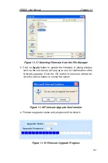
Page 119: ...called an image Web UI Management provides an easy way to upload the new firmware image To upgrade the image follow this procedure 1 Click the System Firmware Upgrade menu to open the Firmware Upgrade page Figure 11 16 Firmware Upgrade Page 2 In the Select Firmware text box enter the path and name of the firmware image file Alternatively you may click on Browse button to open a file manager to sea...

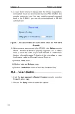
Page 120: ...firmware A dialog window such as the one below will pop up to ask for confirmation of the firmware upgrade Click the OK button to proceed otherwise click the Cancel button to cancel the action Figure 11 18 Firmware Upgrade Confirmation 4 Firmware upgrade status and progress will be shown Figure 11 19 Firmware Upgrade Progress ...

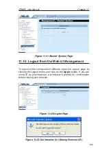
Page 121: ... 6 When you are reconnected to the iPBX30 click Status menu to check if the new firmware is properly upgraded You probably need to clear the cache of your web browser to see the new System Information page Following is the procedure to clear the browser cache for Microsoft Internet Explorer a Click on Tools menu b Click on Internet Options menu c Click on Delete Files button to clear the browser c...

Page 122: ...gement To logout of the configuration software open the Logout page by clicking the Logout menu and click on the Apply button If you are using IE as your browser a window will prompt for confirmation before closing your browser Figure 11 22 Logout Page Figure 11 23 Confirmation for Closing Browser IE ...

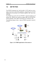
Page 123: ...clients with all necessary call functions together with voice mail capability The iPBX30 can work with any RFC3261 compliant gateway IP phone ATA iPBX30 can connect to legacy PBX by the FXS FXO ports of gateway and is able to handle up to10 concurrent calls The following diagram shows a typical iPBX30 application scenario in office Figure 12 1 iPBX30 application office scenario ...

Page 124: ... Provide media service such as voice mail IVR DISA etc 1 Register to server 2 Make or terminate call via server 3 Voice codec and echo handling 4 C a l l f u n c t i o n handling 5 3 way conferencing 1 Register to server 2 Accept call from server to trunk port FXO FXS or digital trunk T1 E1 DSDN 3 Forward call from trunk to server 4 Voice codec a n d e c h o handling P a r a m e t e r s required 1...

Page 125: ...ocation by checking if it is from external WAN or local LAN SIP codec type Choose one codec type for SIP server from G 711u G 711a G 729A The iPBX30 SIP server uses the selected codec to negotiate with the SIP client requesting for registration The iPBX30 will request every client to use the same codec for compatibility Local subnet This subnet value defines the SIP server LAN segment For example ...

Page 126: ...ed without expire time value attached Start RTP port End RTP port The user can assign the starting RTP port number and End RTP port number for VoIP service to define the iPBX30 VoIP RTP port usage range SIP port The 5060 port is commonly used for SIP call signaling The user can change it if necessary DTMF mode Users can select one of the three available DTMF transmission methods Inband RFC2833 and...

Page 127: ...Assign the gateway IP address to the IP PBX and the outgoing calls can be forwarded to the gateway Seq number Not configurable This field is not configurable and for sequence identification purpose only You may have more than one gateway in an IP PBX system for different call routing with pre defined dialing plans Name This field is for management purpose only IP address Define the proper IP addre...

Page 128: ...ay to be connected to PSTN Trunk or PBX Line extension line or both in a single gateway Location This field allows you to set the location for the gateway 12 1 3 Extensions You can add SIP user accounts in this page The SIP extension accounts must be added before allowing extension client devices for registration You may create up to 30 extensions Some extensions can be used for registering to ITS...

Page 129: ...uration for ITSP operation such as IP address port number assignment ID and password setting Refer to Dialing plan section for more details DTMF mode Select the DTMF mode for this extension to work with the iPBX30 server The available selections are Inband RFC2833 and info Note We recommend using info mode for most cases The SIP client and the server should select the same DTMF mode to work proper...

Page 130: ...ll group This allows the user to assign a group number for identification when this extension makes a call to other parties This will enable another extension to know the group number when it receives a call Pickup group Pickup grouping allows you to group the different extensions with the same working attribute into the same pickup group so the group members can answer their colleague s phone cal...

Page 131: ...m for extension registration Email address When this extension has a voicemail the server will send a email notification to this email address MAC You can give the MAC address of the SIP client device AX 112 for this extension number It is for auto provision function which AX 112 downloads the configuration file from iPBX30 iPBX30 will generate a configuration data file for each extension with the...

Page 132: ...s prefix code It is associated with local privilege in Extensions configuration page Do duplicate with other access code that is already used IDD prefix Define the International Direct Dial prefix code for call privilege control checking It associated with International privilege in Extensions configuration page When an extension is limited and not able to make international long distance call the...

Page 133: ...ink the iPBX30 to ITSP account register the iPBX30 to ITSP and assign an extension number with Auto attendant or ITSP Operator type as the ITSP inbound call operator Figure 12 6 ITSP Server page Seq no Not configurable The iPBX30 allows you to define more than one ITSP service account and this field is used for sequence identification ITSP Address Enter the ITSP server IP address or domain name he...

Page 134: ...n authentication Enter the account name here followed by password and authentication method Authentication The iPBX30 supports MD5 authentication method while registering to ITSP Normally the SIP server registration is protected for preventing unauthorized user login 12 2 3 Prefix Routing Prefix routing enables user to define a prefix code mapping for routing calls to a specified destination The d...

Page 135: ...The available gateways must be predefined in Gateway configuration page Digits to remove The user can define the length of digits to be removed from a call before forwarding to a destination gateway or ITSP server Prefix code removing is necessary because the ITSP will not recognize these codes and may cause call failure Digits to prefix The user can define the length of digits to be added to a ca...

Page 136: ...s page and this page is empty when there is no any extension making calls or ITSP gateway activities in progressing 12 3 3 ITSP registry If you have ITSP SIP account and it is properly setup you can check the ITSP registration status here The iPBX30 keeps trying to register to ITSP account until it is successful The iPBX30 allows you to register to multiple ITSP accounts at the same time Figure 12...

Page 137: ...tems are much more sophisticated than answering machines in that they can Answer many phones at the same time Store incoming voice messages in personalized mailboxes associated with the user s phone number Enable users to forward received messages to another voice mailbox Store voice messages for future delivery Send email to notify the uset a message has arrived in the mailbox Transfer callers to...

Page 138: ... email Sender field SMTP Servers SMTP Port The iPBX30 uses this SMTP Server to send the email notification out SMTP Authentication Type The iPBX30 supports two authentication types to mail server LOGIN and PLAIN There is 8Mbytes space for voice message as default and the recording time depends on the voice codec you selected G 711 uLaw aLaw is 8K bytes per second and G 729 is 1K bytes per second I...

Page 139: ...our voice message 1 Dial 8500 from your IP phone to enter iPBX30 voicemail box function main menu 2 Enter the extension number and password to access your message after entering voicemail box 3 The password is identical to the registration password which you set up in the Extension page Refer to section 12 1 3 Extension 4 Follow the voice prompt for more operation Voice mail function main menu flo...

Page 140: ...7 Press 1 to enter play back message menu and refer to the following flowchart To enter message option menu press 3 in the message option menu after message played You can select to reply message to caller or repeat the message again ...

Page 141: ... is no standard algorithm for provisioning so it s nature that iPBX30 only supports the device now Autoprovision function allows system maintainer to define the configuration data for SIP client devices on iPBX30 server GUI This function can minimize the deployment efforts of ATA IP phone and increase the consistence and flexibility when replacing client devices The iPBX30 must have a copy of conf...

Page 142: ...X30 USB port If an USB storage device has been configured for CDR and voice mail then the records data will not be lost when iPBX30 is powered off 12 6 Utilities 12 6 1 Hot reload Every time you make changes on the IP PBX settings you have to tell the IP PBX server to reload the new configuration and activate Click the confirm button and the reload process will begin taking about 10 seconds to loa...

Page 143: ...x Two AX 112 ATA in LAN with extension number 1001 1002 and the AX 112 WAN is in DHCP client mode this means AX 112 will get IP from iPBX30 built in DHCP server One AX 112 ATA in Internet with extension number 1003 and its WAN IP is 192 168 10 10 which is obtained from the home router One SIP gateway connected to PSTN lines with LAN IP 192 192 1 10 Figure 12 12 Typical iPBX30 application set up 12...

Page 144: ...ices Click IP PBX Configuration Extensions to open the page as shown below Figure 12 13 Extension List page Click the Add button to open the extension configuration page Figure 12 14 Extension page We recommend you set up parameters for extension 1001 as following 1 Set Extension Caller ID Password to 1001 2 Check Type as SIP DTMF mode as Info ...

Page 145: ...Yes 7 After all setting are completed click Utility item from the left side menu and click Hot reload to make iPBX30 reload all the settings and take effective Figure 12 15 SIP page To configure the SIP client devices 1 Connect AX 112 to iPBX30 using RJ45 cable connect an analog phone set to AX 112 using RJ11 cable and power on AX 112 2 Pick up the phone and dial to hear AX 112 IVR Interactive Voi...

Page 146: ...ere are 3 steps to enable ITSP service Create an extension for ITSP It is necessary for iPBX30 to use an extension as an UA User Agent to register to ITSP SIP server and also to accept the incoming call from ITSP Select an extension number for ITSP registration and click the type as ITSP operator Set up ITSP account Enter the ITSP server public IP address or domain name and the proper user name an...

Page 147: ... dots is called dotted decimal notation The IP address 20 56 0 211 is read twenty dot fifty six dot zero dot two eleven 13 1 1 Structure of an IP address IP addresses have a hierarchical design similar to that of telephone numbers For example a 7 digit telephone number starts with a 3 digit prefix that identifies a group of thousands of telephone lines and ends with four digits that identify one s...

Page 148: ... these huge networks can exist for a total of over 2 billion hosts Because of their huge size these networks are used for WANs and by organizations at the infrastructure level of the Internet such as your ISP Class B networks are smaller but still quite large each able to hold over 65 000 hosts There can be up to 16 384 class B networks in existence A class B network might be appropriate for a lar...

Page 149: ...u would use the subnet mask 255 255 255 128 It s easier to see what s happening if we write this in binary 11111111 11111111 11111111 10000000 As with any class C address all of the bits in field1 through field 3 are part of the network ID but note how the mask specifies that the first bit in field 4 is also included Since this extra bit has only two values 0 and 1 this means there are two subnets...

Page 150: ...0 User Manual Chapter 13 137 Class A 255 0 0 0 Class B 255 255 0 0 Class C 255 255 255 0 These are called default because they are used when a network is initially configured at which time it has no subnets ...

Page 151: ......
Page 152: ...t power strip LINK WAN LED does not light up after Ethernet cable is attached Verify that an Ethernet cable like the one provided is securely connected to the Ethernet port of your ADSL or cable modem and the WAN port of the iPBX30 Make sure that your ADSL or cable mo dem is powered on Wait 30 seconds to allow the iPBX30 to negotiate a connection with your broad band modem LINK LAN LED does not li...

Page 153: ...our ISP that the DNS server specified for the PC is valid Correct the address or configure the PC to receive this information automatically Verify that a Network Address Translation rule has been defined on the IPBX30 to translate the private address to your public IP address The assigned IP address must be within the range specified in the NAT rules Or configure the PC to accept an address assign...

Page 154: ... to their default values Cannot access the Web UI Management program from your browser Use the ping utility discussed in the following sec tion to check whether your PC can communicate with the iPBX30 s LAN IP address by default 192 168 1 1 If it cannot check the Ethernet ca bling Verify that you are using Internet Explorer 6 0 or newer Support for Javascript must be enabled in your browser Suppor...

Page 155: ...itute any private IP address on your LAN or a public IP address for an Internet site if known Figure 14 1 Using the ping utility C ping 192 168 1 1 Pinging 192 168 1 1 with 32 bytes of data Reply from 192 168 1 1 bytes 32 time 10ms TTL 225 Reply from 192 168 1 1 bytes 32 time 10ms TTL 225 Reply from 192 168 1 1 bytes 32 time 10ms TTL 225 Reply from 192 168 1 1 bytes 32 time 10ms TTL 225 Ping stati...

Page 156: ... Aliases www abcsnew com You can use the nslookup command to determine the IP address associated with an Internet site name You specify the common name and the nslookup command looks up the name on your DNS server usually located with your ISP If that name is not an entry in your ISP s DNS table the request is then referred to another higher level server and so on until the entry is found The serv...

Page 157: ...eral addresses associated with an Internet name This is common for web sites that receive heavy traffic they use multiple redundant servers to carry the same information To exit from the nslookup utility type exit and press Enter at the command prompt ...

Page 158: ...ed addresses 48 DHCP Server Configuration page 46 Diagnosing problems after installation 21 DMZ IP address 29 DNS 50 defined 50 relay 51 Domain Name System See DNS Dynamically assigned IP addresses 36 Eth 0 interface defined 22 Ethernet cable 12 Features 1 Firmware Upgrade page 106 Firmware upgrades 106 Front panel 8 Gateways in DHCP pools 45 Gateway defined 53 Hardware connections 12 13 Host ID 1...

Page 159: ...PAT 65 Reverse NAPT 67 Virtual Server 67 Navigating 26 Netmask See Network mask Network classes 135 Network ID 135 Network interface card 1 Network mask 135 Network Setup 28 Network Setup Configuration page 28 Node on network defined 27 Notational conventions 1 nslookup 143 Packet filtering 63 Pages DHCP Address Table 47 DHCP Lease Table 49 DHCP Server Configuration 46 Firmware Upgrade Upgrade 106...

Page 160: ... Route Configuration page 56 Static routes adding 57 Statically assigned IP addresses 45 Subnet masks 109 System requirements for Web UI Management 23 System requirements 1 System Status page 21 Testing setup 21 Time and date changing 92 Troubleshooting 139 Typographical conventions 1 Upgrading firmware 106 User Password Configuration page 97 Username default 19 24 WAN DHCP 29 WAN IP address 29 We...

Reviews: