background image


ASUS JIG Board User Manual 
 

ASUSTeK Confidential 

                            15                                                          October 14, 2011 


5

  Read Target board’s BIOS ROM 

5.1  Read Target board’s BIOS ROM via SPI extend card 

if the manufacturer of EC is ENE 


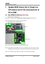
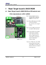
Step 1: Remove all power sources 

(include battery and power 

supply)

 from target board. 


Step 2: Plug in SPI extend card to JIG3 

extend port(CON301). 

Note: Extend card not support 

hotplug. 


Step 3: Connect USB cable from CN1 

to your PC’s USB connector. 


Step 4: Connect FPC cable from SPI 

extend card to your target 

board’s keyboard connector, 

make sure SPI extend card 

connect Pin1 is connected to 

target board keyboard 

connector’s Pin1. 


Step5: Use a USB cable connect GND 

between JIG3 CN2 and target 

board USB port, and make sure 

all power sources was removed 

form target board. 


GND 

SPI Ext. Card 

USB 

JIG Board Extend connecter 

EPC 

JIG Board 

NB 

Step 2 

Summary of Contents for JIG 3

Page 1: ...ument contains information proprietary to ASUSTeK Computer Inc Use or disclosure without permission of an offer of ASUSTeK is expressly forbidden JIG 3 SPI EXTEND CARD User Manual Released by Chris Gao Firmware R D Center Revision 1 0 0 5 October 14 2011 ...

Page 2: ...e manufacturer of EC is ITE 14 5 Read Target board s BIOS ROM 15 5 1 Read Target board s BIOS ROM via SPI extend card if the manufacturer of EC is ENE 15 5 2 Read Target board s BIOS ROM if the manufacturer of EC is ITE 18 6 Example 19 6 1 Update BIOS binary file to Target on ShareROM architecture via SPI extend card if the manufacturer of EC is ENE 19 6 2 Read Target board s BIOS ROM 24 7 Appendi...

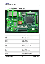
Page 3: ...ET button BTN3 Start button BTN4 Function button LED1 Software On Power LED LED2 Good Fail Busy PWR LED LED3 Function indicator LED LED4 Message ID LED indicator SW1 Function Switch U1 SPI Flash IC J301 UP connect connector J302 Down connect connector CON301 JIG board Extend connector CN1 CN2 BTN1 BTN2 LED1 BTN3 BTN4 LED3 LED4 LED2 U1 SW1 J301 J302 CON301 ...

Page 4: ... keyboard Down connector NSU Notebook Small keyboard Up connector NBU Notebook Big keyboard Up connector EBD EPC Big keyboard Down connector ESU EPC Small keyboard Up connector ESD EPC Small keyboard Down connector EBU EPC Big keyboard Up connector JIG board Extend connector NSD NBD ESD EBD To Notebook To EPC ESU To Notebook NBU NSU EBU JIG board Extend connector ...

Page 5: ...t board Step 2 Plug in SPI extend card to JIG3 extend port CON301 Note Extend card not support hotplug Step 3 Connect USB cable from CN1 to your PC s USB connector Step 4 Connect FPC cable from SPI extend card to your target board s keyboard connector make sure SPI extend card connect Pin1 is connected to target board keyboard connector s Pin1 Step 5 Use a USB cable connect GND between JIG3 CN2 an...

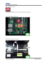
Page 6: ...ser Manual ASUSTeK Confidential 5 October 14 2011 Step 6 Set SW1 to 0000 Step 7 Press POWER button to turn on power Power led will turn on Step 8 Check LED4 will show 00 Step9 Check all connecter are ready Step8 Step9 ...

Page 7: ...2011 Step 10 Run ASUS_WinFlash utility Step 11 The Log will show the project name that have connect target board and SPI extend card If it didn t be connected yet please exit ASUS_WinFlash and go to Step1 Step 12 Check the Architecture Check Step 11 Check Step 12 ...

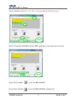
Page 8: ...ice Asus JIG3 is Plug In and Flash of SPI extend card Step 14 Check Protect NVRAM to Protect GPNV Appendix A Can choose protect it or not Step 15 Press LoadFile icon to load BIOS ROM file Step 16 Press AutoBurn icon to burn BIOS ROM file to Target board Check Check Check Step 13 Step 14 Check ...

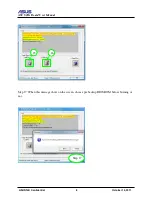
Page 9: ...ASUS JIG Board User Manual ASUSTeK Confidential 8 October 14 2011 Step 17 When this message show on the screen choose pre backup BIOS ROM before burning or not 16 15 Step 17 ...

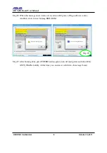
Page 10: ... message show on the screen turn on EC power Plug on Power source And then show to start burning BIOS ROM Step 19 After burning done press POWER button again to turn off main power and turn off the ASUS_WinFlash utility At this time you can remove all devices form target board Step 18 ...

Page 11: ...files Please reference Appendix A Step 1 Step14 The same as chapter 3 1 Step 15 Press LoadFile icon to load EC ROM BIOS ROM file Step 16 Press AutoBurn icon to burn EC ROM BIOS ROM file to Target board Step 17 When this message show on the screen choose pre backup BIOS ROM before burning or not Step 17 ...

Page 12: ... Board User Manual ASUSTeK Confidential 11 October 14 2011 Step 18 When this message show on the screen turn on EC power Plug on Power source Step 19 This message notify to start burning EC ROM Step 18 Step 19 ...

Page 13: ...STeK Confidential 12 October 14 2011 Step 20 When this message show on the screen turn off EC power Plug out Power source Step 21 When this message show on the screen turn on EC power again Plug on Power source again Step 21 Step 20 ...

Page 14: ...3 October 14 2011 Step 22 This message notify to start burning BIOS ROM Step 23 After burning done press POWER button again to turn off main power and turn off the ASUS_WinFlash utility At this time you can remove all devices form target board Step 22 ...

Page 15: ...ASUS JIG Board User Manual ASUSTeK Confidential 14 October 14 2011 4 Update BIOS binary file to Target if the manufacturer of EC is ITE Please reference another SOP ...

Page 16: ...xtend port CON301 Note Extend card not support hotplug Step 3 Connect USB cable from CN1 to your PC s USB connector Step 4 Connect FPC cable from SPI extend card to your target board s keyboard connector make sure SPI extend card connect Pin1 is connected to target board keyboard connector s Pin1 Step5 Use a USB cable connect GND between JIG3 CN2 and target board USB port and make sure all power s...

Page 17: ... Step 8 Check LED4 will show 00 Step 9 Run ASUS_WinFlash utility Step 10 The Log will show the project name that have connect target board and SPI extend card If it didn t be connected yet please exit ASUS_WinFlash and go to Step2 Step 11 Check the USB Device Asus JIG3 is Plug In and Flash of SPI extend card Check Check Check Check Step 8 Step 11 Step 10 ...

Page 18: ...S ROM from target board Step 13 When this message show on the screen turn on EC power Plug on Power source Step 14 After read BIOS ROM from target board press POWER button again to turn off main power and turn off the ASUS_WinFlash utility At this time you can remove all devices form target board 12 Step 13 ...

Page 19: ...ASUS JIG Board User Manual ASUSTeK Confidential 18 October 14 2011 5 2 Read Target board s BIOS ROM if the manufacturer of EC is ITE Please reference another SOP ...

Page 20: ...ntial 19 October 14 2011 6 Example 6 1 Update BIOS binary file to Target on ShareROM architecture via SPI extend card if the manufacturer of EC is ENE Remove all power sources Connect all cable and turn on JIG3 power Step 1 3 2 5 6 8 4 Step 2 8 ...

Page 21: ...ASUS JIG Board User Manual ASUSTeK Confidential 20 October 14 2011 Check all connecter Run ASUS_WinFlash utility and check all information Check Check Check Step 10 13 Check Step 9 ...

Page 22: ...ASUS JIG Board User Manual ASUSTeK Confidential 21 October 14 2011 Check Protect NVRAM to Protect GPNV Appendix A Load file Step 14 Step 15 15 Check ...

Page 23: ...Manual ASUSTeK Confidential 22 October 14 2011 Press AutoBurn and when this message show on the screen choose pre backup BIOS ROM before burning or not When this message show on the screen turn on EC power Step 18 Step 17 ...

Page 24: ...ASUS JIG Board User Manual ASUSTeK Confidential 23 October 14 2011 Turn on EC power After burning done check Auto Flash OK Step 18 Step 19 Check ...

Page 25: ...oard User Manual ASUSTeK Confidential 24 October 14 2011 6 2 Read Target board s BIOS ROM The Step 1 11 is the same as chapter 4 1 Press ReadRom and turn on EC power After reading save file Step 12 13 12 Step 14 ...

Page 26: ...ASUS JIG Board User Manual ASUSTeK Confidential 25 October 14 2011 7 Appendix A KeyBoard Connector Up Connector The pin connect on the up side Down Connector The pin connect on the down side ...

Page 27: ...US JIG Board User Manual ASUSTeK Confidential 26 October 14 2011 KeyBoard Type Big Keyboard keyboard have extend numeric keypad Small Keyboard keyboard have no extend numeric keypad extend numeric keypad ...

Page 28: ...ober 14 2011 EC Manufacturer ID EC ENE The Manufacturer of EC is ENE EC ITE The Manufacturer of EC is ITE Platform Platform HR The platform is Huron River Normally the manufacturer of EC on Huron River is ITE Platform NONHR The platform is not Huron River ...

Page 29: ...C ROM and the BIOS ROM are not the same ROM So there are two files that have to burn ECROM file must be burned on EC ROM first And then burn BIOSBIN file to BIOS ROM GPNV GPNV is one of the BIOS ROM sections that have important information So when Protect NVRAM checked we will protect this section can t be replaced GPNV is searched by the index BIOSINFO Normally it only can use after Huron River p...

Page 30: ...ctober 14 2011 Appendix B Build ENEProjectList ini file Step 1 Open the ENEProjectList ini in the file path INI ENEProjectList ini Step 2 Type Project Name into that all of the manufacturer of EC in these projects are ENE ex TestProject1 Step 3 Save file ...

Reviews: