background image

A S U S   K 8 S - L A   ( S a l m o n )

A S U S   K 8 S - L A   ( S a l m o n )

A S U S   K 8 S - L A   ( S a l m o n )

A S U S   K 8 S - L A   ( S a l m o n )

A S U S   K 8 S - L A   ( S a l m o n )

9

9

9

9

9

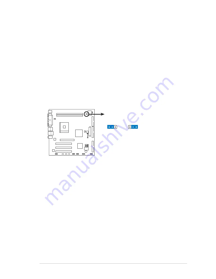
Clear password (3-pin J7)

Clear password (3-pin J7)

Clear password (3-pin J7)

Clear password (3-pin J7)

Clear password (3-pin J7)

This jumper allows you to clear the  password if you forgot your
password.

To erase the password:

1. Turn OFF the computer and unplug the power cord.
2. Move the jumper cap from pins 2-3 (Normal) to pins 1-2 (Clear

Password).

3. Plug the power cord and turn ON the computer.
4. As soon as you see the HP logo, turn OFF the computer.
5. Move the jumper cap from pins 1-2 to pins 2-3.

6. Hold down the <F1> key during the boot process and enter BIOS

setup to verify that the password has been cleared.

K8S-LA

K8S-LA Clear password setting

J7

Normal

Clear Password

(Default)

2 3

1 2

Summary of Contents for K8S-LA (Salmon)

Page 1: ...Motherboard K8S LA Salmon ...

Page 2: ...ontents K8S LA specifications summary iii 1 Motherboard layout 1 2 Central Processing Unit CPU 2 3 System memory 4 4 Expansion slots 6 5 Jumpers 8 6 Connectors 9 6 1 Rear panel connectors 9 6 2 Internal connectors 11 ...

Page 3: ...x Parallel port 1 x IEEE 1394a port 1 x LAN RJ 45 port 6 channel audio ports 4 x USB 2 0 ports 1 x VGA port 1 x Serial port 1 x PS 2 keyboard port C P U C P U C P U C P U C P U Chipset Chipset Chipset Chipset Chipset Front Side Bus FSB Front Side Bus FSB Front Side Bus FSB Front Side Bus FSB Front Side Bus FSB Memory Memory Memory Memory Memory Expansion slots Expansion slots Expansion slots Expan...

Page 4: ... connector 2 x Serial ATA connectors 1 x IEEE 1394a connector 2 x USB 2 0 connectors support for four additional USB 2 0 ports 1 x CPU fan connector 1 x Chassis fan connector 1 x CD in connector 1 x AUX connector 1 x SPDIF out connector 1 x Front panel audio connector System panel connector Internal connectors Internal connectors Internal connectors Internal connectors Internal connectors ...

Page 5: ...4Mb BIOS PCI 1 Realtek VT6307 CHA_FAN1 24 5cm 9 64in SECONDARY_IDE 1394 Top USB1 USB2 Bottom J6 BUZZ1 BATY1 J7 USB1 DDR XMM2 64 72 bit 184 pin module DDR XMM1 64 72 bit 184 pin module PS 2 T Mouse B Keyboard Below Mic In Center Line Out Top Line In RJ 45 Top USB1 USB2 Bottom PCI 2 PCI 3 ALC658 F_PANEL1 ATX12V1 PRIMARY_IDE CPU_FAN1 SPDIF1 AUX1 CD1 J3 IEEE1394_1 COM1 PARALLEL PORT VGA USB2 SiS 760 C...

Page 6: ... 2 1 Installing the CPU Installing the CPU Installing the CPU Installing the CPU Installing the CPU Follow these steps to install a CPU 1 Locate the 754 pin ZIF socket on the motherboard 2 Central Processing Unit CPU The motherboard comes with a surface mount 754 pin Zero Insertion Force ZIF socket designed for the AMD Athlon 64 processor Take note of the marked corner with gold triangle on the CP...

Page 7: ...ully insert the CPU into the socket until it fits in place 5 When the CPU is in place push down the socket lever to secure the CPU The lever clicks on the side tab to indicate that it is locked 6 Install a CPU heatsink and fan following the instructions that came with the heatsink package 7 Connect the CPU fan cable to the CPU_FAN connector on the motherboard G o l d G o l d G o l d G o l d G o l ...

Page 8: ...00 double sided DDR DIMMs The following figure illustrates the location of the DDR DIMM sockets Memory configurations Memory configurations Memory configurations Memory configurations Memory configurations You can install 128 MB 256 MB 512 MB and 1 GB DDR DIMMs into the DIMM sockets using the memory configurations in this section K8S LA K8S LA 184 pin DDR DIMM sockets 80 Pins 104 Pins A DDR DIMM i...

Page 9: ...ynchronization Memory frequency CPU FSB synchronization Memory frequency CPU FSB synchronization Memory frequency CPU FSB synchronization Memory frequency CPU FSB synchronization Use only identical DDR DIMM pairs Use only identical DDR DIMM pairs Use only identical DDR DIMM pairs Use only identical DDR DIMM pairs Use only identical DDR DIMM pairs C P U F S B C P U F S B C P U F S B C P U F S B C P...

Page 10: ...Q assignments for this motherboard IRQ assignments for this motherboard IRQ assignments for this motherboard IRQ assignments for this motherboard A B C D E F PCI slot 1 shared PCI slot 2 used PCI slot 3 used AGP slot shared Onboard VT6307 1394a controller shared I R Q I R Q I R Q I R Q I R Q Priority Priority Priority Priority Priority Standard Function Standard Function Standard Function Standard...

Page 11: ...re IRQ or that the cards do not need IRQ assignments Otherwise conflicts will arise between the two PCI groups making the system unstable and the card inoperable AGP slot AGP slot AGP slot AGP slot AGP slot This motherboard has an Accelerated Graphics Port AGP slot that supports 1 5V AGP cards When you buy an AGP card make sure that you ask for one with 1 5V specification Note the notches on the c...

Page 12: ...rs the RAM data in CMOS which include system setup information such as system passwords To erase the RTC RAM 1 Turn OFF the computer and unplug the power cord 2 Move the jumper cap from pins 2 3 Normal to pins 1 2 Clear CMOS Keep the cap on pins 2 3 for about 5 10 seconds then move the cap back to pins 2 3 3 Plug the power cord and turn ON the computer 4 Hold down the F1 key during the boot proces...

Page 13: ...password To erase the password 1 Turn OFF the computer and unplug the power cord 2 Move the jumper cap from pins 2 3 Normal to pins 1 2 Clear Password 3 Plug the power cord and turn ON the computer 4 As soon as you see the HP logo turn OFF the computer 5 Move the jumper cap from pins 1 2 to pins 2 3 6 Hold down the F1 key during the boot process and enter BIOS setup to verify that the password has...

Page 14: ...etwork LAN through a network hub 5 5 5 5 5 Line In port light blue Line In port light blue Line In port light blue Line In port light blue Line In port light blue This port connects a tape CD DVD player or other audio sources 6 6 6 6 6 Line Out port lime Line Out port lime Line Out port lime Line Out port lime Line Out port lime This port connects a headphone or a speaker In 4 channel or 6 channel...

Page 15: ...nd 2 These two 4 pin Universal Serial Bus USB ports are available for connecting USB 2 0 devices 10 10 10 10 10 Video Graphics Adapter port Video Graphics Adapter port Video Graphics Adapter port Video Graphics Adapter port Video Graphics Adapter port This 15 pin port is for a VGA monitor or other VGA compatible devices 11 11 11 11 11 Serial port Serial port Serial port Serial port Serial port Thi...

Page 16: ...ctor 34 1 pin FLOPPY1 Floppy disk drive connector 34 1 pin FLOPPY1 Floppy disk drive connector 34 1 pin FLOPPY1 Floppy disk drive connector 34 1 pin FLOPPY1 This connector is for the provided floppy disk drive FDD signal cable Insert one end of the cable to this connector then connect the other end to the signal connector at the back of the floppy disk drive Pin 5 on the connector is removed to pr...

Page 17: ...he motherboard a black connector for an Ultra DMA 100 66 IDE slave device optical drive hard disk drive and a gray connector for an Ultra DMA 100 66 IDE master device hard disk drive If you install two hard disk drives you must configure the second drive as a slave device by setting its jumper accordingly Refer to the hard disk documentation for the jumper settings Pin 20 on the IDE connector is r...

Page 18: ...ion and push down firmly until the connectors completely fit Do not forget to connect the 4 pin ATX 12 V power plug otherwise the system will not boot up Make sure that your ATX 12V power supply can provide 8A on the 12V lead and at least 1A on the 5 volt standby lead 5VSB The minimum recommended wattage is 230W or 300W for a fully configured system The system can become unstable and might experie...

Page 19: ... S S S Standard IDE tandard IDE tandard IDE tandard IDE tandard IDE mode connect the primary boot hard disk drive to the SATA1 connector Refer to the table below for the recommended SATA hard disk drive connections Connector Connector Connector Connector Connector C o l o r C o l o r C o l o r C o l o r C o l o r S e t t i n g S e t t i n g S e t t i n g S e t t i n g S e t t i n g U s e U s e U s...

Page 20: ...8S LA K8S LA IEEE 1394 connector IEEE1394_1 1 TPA0 GND TPB0 12V GND TPA0 GND TPB0 12V Never connect a 1394 cable 1394 cable 1394 cable 1394 cable 1394 cable to the USB connectors Doing so will damage the motherboard 6 6 6 6 6 USB connectors 10 1 pin USB1 USB2 USB connectors 10 1 pin USB1 USB2 USB connectors 10 1 pin USB1 USB2 USB connectors 10 1 pin USB1 USB2 USB connectors 10 1 pin USB1 USB2 Thes...

Page 21: ...ble matches the ground pin of the connector Do not forget to connect the fan cables to the fan connectors Insufficient air flow inside the system may damage the motherboard components These are not jumpers Do not place jumper caps on the fan connectors K8S LA K8S LA Fan connectors CHA_FAN1 CPU_FAN1 GND Rotation 12V GND Rotation 12V 8 8 8 8 8 Internal audio connectors 4 pin CD1 AUX1 Internal audio ...

Page 22: ...tal Interface S PDIF port Connect the S PDIF module cable to this connector then install the module to a slot opening at the back of the system chassis The S PDIF module is purchased separately K8S LA K8S LA Front panel audio connector J3 BLINE_OUT_L MIC2 Line out_R Line out_L BLINE_OUT_R NC MICPWR 5VA AGND 10 10 10 10 10 Front panel audio connector 10 1 pin J3 Front panel audio connector 10 1 pin...

Page 23: ...on 2 pin PWRBTN ATX power button soft off button 2 pin PWRBTN ATX power button soft off button 2 pin PWRBTN ATX power button soft off button 2 pin PWRBTN ATX power button soft off button 2 pin PWRBTN This connector is for the system power button Pressing the power button turns the system on or puts the system in sleep or soft off mode depending on the BIOS settings Pressing the power switch for mo...

Page 24: ...2 0 2 0 2 0 2 0 2 0 ASUS K8S LA Salmon ASUS K8S LA Salmon ASUS K8S LA Salmon ASUS K8S LA Salmon ASUS K8S LA Salmon ...

Reviews: