
ASUS M3A
2-15
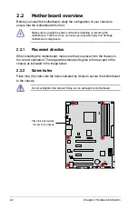
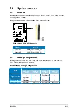
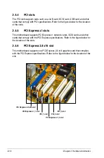
2.4.3
Installing a DIMM
Unplug the power supply before adding or removing DIMMs or other
system components. Failure to do so can cause severe damage to both the
motherboard and the components.
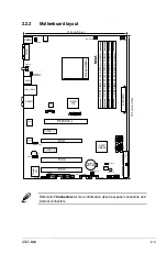
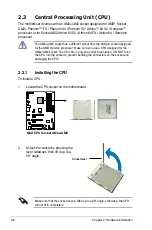
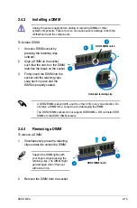
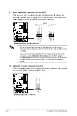
To install a DIMM:
1. Unlock a DIMM socket by
pressing the retaining clips
outward.
2. Align a DIMM on the socket
such that the notch on the DIMM
matches the break on the socket.
3. Firmly insert the DIMM into the
socket until the retaining clips
snap back in place and the
DIMM is properly seated.
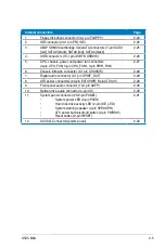
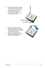
2.4.4
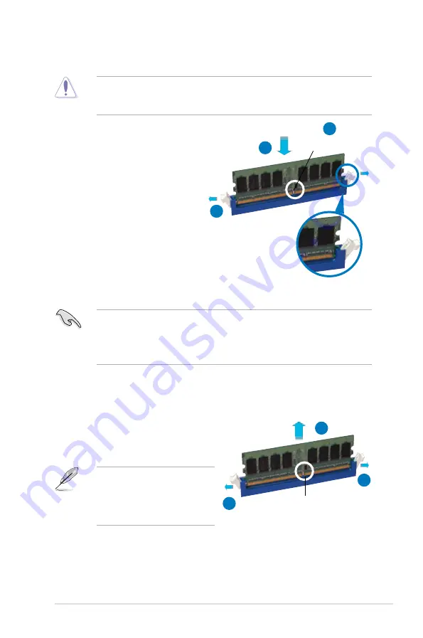
Removing a DIMM
To remove a DIMM:
1. Simultaneously press the retaining
clips outward to unlock the DIMM.
2. Remove the DIMM from the socket.
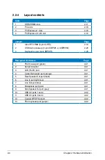
• A DDR2 DIMM is keyed with a notch so that it fits in only one direction. Do
not force a DIMM into a socket to avoid damaging the DIMM.
• The DDR2 DIMM sockets do not support DDR DIMMs. DO not install DDR
DIMMs to the DDR2 DIMM sockets.
Support the DIMM lightly with
your fingers when pressing the
retaining clips. The DIMM might
get damaged when it flips out
with extra force.
1
2
1
DDR2 DIMM notch
Unlocked retaining clip
DDR2 DIMM notch
1
2
3


