background image

Motherboard

M4A78-VM IN/SI

Summary of Contents for M4A78-VM IN SI

Page 1: ...Motherboard M4A78 VM IN SI ...

Page 2: ...RTICULAR PURPOSE IN NO EVENT SHALL ASUS ITS DIRECTORS OFFICERS EMPLOYEES OR AGENTS BE LIABLE FOR ANY INDIRECT SPECIAL INCIDENTAL OR CONSEQUENTIAL DAMAGES INCLUDING DAMAGES FOR LOSS OF PROFITS LOSS OF BUSINESS LOSS OF USE OR DATA INTERRUPTION OF BUSINESS AND THE LIKE EVEN IF ASUS HAS BEEN ADVISED OF THE POSSIBILITY OF SUCH DAMAGES ARISING FROM ANY DEFECT OR ERROR IN THIS MANUAL OR PRODUCT SPECIFICA...

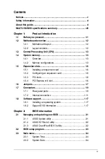
Page 3: ...1 5 1 Installing an expansion card 1 6 1 5 2 Configuring an expansion card 1 6 1 5 3 PCI slots 1 6 1 5 4 PCI Express x16 slot 1 6 1 6 Jumpers 1 7 1 7 Connectors 1 9 1 7 1 Rear panel ports 1 9 1 7 2 Internal connectors 1 11 1 8 Software support 1 17 1 8 1 Installing an operating system 1 17 1 8 2 Support DVD information 1 17 Chapter 2 BIOS information 2 1 Managing and updating your BIOS 2 1 2 1 1 A...

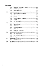
Page 4: ...4 4 Onboard Devices Configuration 2 9 2 4 5 PCI PnP 2 9 2 4 6 USB Configuration 2 9 2 5 Power menu 2 10 2 5 1 Suspend Mode 2 10 2 5 2 ACPI 2 0 Support 2 10 2 5 3 ACPI APIC Support 2 10 2 5 4 APM Configuration 2 11 2 5 5 HW Monitor Configuration 2 11 2 6 Boot menu 2 12 2 6 1 Boot Device Priority 2 12 2 6 2 Boot Settings Configuration 2 12 2 6 3 Security 2 13 2 7 Tools menu 2 14 2 7 1 ASUS EZ Flash ...

Page 5: ... from that to which the receiver is connected Consult the dealer or an experienced radio TV technician for help The use of shielded cables for connection of the monitor to the graphics card is required to assure compliance with FCC regulations Changes or modifications to this unit not expressly approved by the party responsible for compliance could void the user s authority to operate this equipme...

Page 6: ...eration safety Before installing the motherboard and adding devices on it carefully read all the manuals that came with the package Before using the product ensure that all cables are correctly connected and the power cables are not damaged If you detect any damage contact your dealer immediately To avoid short circuits keep paper clips screws and staples away from connectors slots sockets and cir...

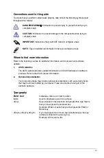
Page 7: ...ct and software updates 1 ASUS websites The ASUS website provides updated information on ASUS hardware and software products Refer to the ASUS contact information 2 Optional documentation Your product package may include optional documentation such as warranty flyers that may have been added by your dealer These documents are not part of the standard package Typography Bold text Indicates a menu o...

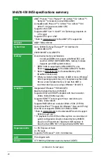
Page 8: ...List When you install a total memory of 4GB or more Windows 32 bit operating system may only recognize less than 3GB Hence a total installed memory of less than 3GB is recommended if you are using a Windows 32 bit OS Graphics Integrated ATI Radeon HD3200 GPU Maximum shared memory of 256 MB Supports DVI D with HDCP compliant with max resolution 2560 x 1600 60Hz dual link Supports HDMI Technology wi...

Page 9: ...RJ 45 port 4 x USB 2 0 1 1 ports 6 channel audio I O ports Internal I O connectors 2 x USB 2 0 1 1 connectors support additional 4 USB 2 0 1 1 ports 1 x IDE connector 1 x COM connector 4 x SATA connectors 1 x High definition front panel audio connector 1 x System panel connector 1 x Chassis intrusion connector 1 x S PDIF Out connector 1 x CPU Chassis Power fan connectors 1 x LPT connector optional...

Page 10: ...ect such as the power supply case to avoid damaging them due to static electricity Hold components by the edges to avoid touching the ICs on them Whenever you uninstall any component place it on a grounded antistatic pad or in the bag that came with the component Before you install or remove any component switch off the ATX power supply and detach its power cord Failure to do so may cause severe d...

Page 11: ...SW setting 30 pin HDSW 1 8 11 Serial ATA connectors 7 pin SATA1 4 1 11 3 USB device wake up 3 pin USBPW1 4 3 pin USBPW5 8 1 8 12 System panel connector 10 1 pin F_PANEL 1 16 4 ATX power connectors 24 pin EATXPWR 4 pin ATX12V 1 15 13 USB connectors 10 1 pin USB56 USB78 1 13 5 Power CPU and chassis fan connectors 3 pin PWR_FAN 4 pin CPU_FAN 3 pin CHA_FAN 1 14 14 Clear RTC RAM 3 pin CLRTC 1 7 6 CPU S...

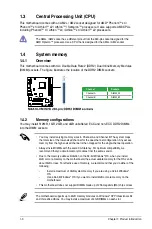
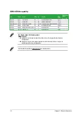
Page 12: ...of the following Install a maximum of 3GB system memory if you are using a 32 bit Windows OS Use a 64 bit Windows OS if you want to install 4GB or more memory on the motherboard This motherboard does not support DIMMs made up of 256 megabits Mb chips or less 1 4 2 Memory configurations You may install 512MB 1GB 2GB and 4GB unbuffered ECC and non ECC DDR2 DIMMs into the DIMM sockets Channel Sockets...

Page 13: ...3R1GE3FGF907MAT0FTAIWAN G8E PSC 1024MB Qimonda HYS64T128000EU 1 9 C2 DS N A HYB18T1G800C2F 1 9FSS25253 Qimonda 2048MB Kit of 2 Transcend TX1066QLU 2GK SS 5 Heat Sink Package N A Size Vendor Part No SS DS CL Chip NO Chip Brand DIMM sockets support A B 2048MB Kit of 2 A Data AD2800E001G0U SS 4 4 4 12 Heat Sink Package N A 512MB Apacer 78 91G91 9K5 SS 5 AM4B5708JQJS8E0751C Apacer 1024MB Corsair XMS2 ...

Page 14: ...Kingmax KLCD48F A8KB5 DS N A KKEA88B4LAUG 29DX Kingmax 1024MB Kingston KVR667D2N5 1G low profile DS 5 E5108AJBG 8E E PSC 1024MB Transcend JM667QLJ 1G DS 5 E5108AJBG 6E E Elpida SS Single sided DS Double sided DIMM support A Supports one module inserted into either slot as the single channel memory configuration B Supports one pair of modules inserted into both the blue slots as one pair of dual ch...

Page 15: ... seated on the slot 5 Secure the card to the chassis with the screw 6 Replace the chassis cover 1 5 2 Configuring an expansion card After installing the expansion card configure it by adjusting the software settings 1 Turn on the system and change the necessary BIOS settings if any See Chapter 2 for information on BIOS setup 2 Assign an IRQ to the card 3 Install the software drivers for the expans...

Page 16: ...TC jumper default position Removing the cap will cause system boot failure To erase the RTC RAM 1 Turn OFF the computer and unplug the power cord 2 Move the jumper cap from pins 1 2 default to pins 2 3 Keep the cap on pins 2 3 for about 5 10 seconds then move the cap back to pins 1 2 3 Plug the power cord and turn ON the computer 4 Hold down the Del key during the boot process and enter BIOS setup...

Page 17: ...e USB device wake up feature requires a power supply that can provide 500mA on the 5VSB lead for each USB port otherwise the system would not power up The total current consumed must NOT exceed the power supply capability 5VSB whether under normal condition or in sleep mode 4 HDSW setting 30 pin HDSW This jumper allows you to switch between the HDMI and the DVI features By default the HDMI feature...

Page 18: ...ight Blue Line In Rear Speaker Out Rear Speaker Out Lime Line Out Front Speaker Out Front Speaker Out Pink Mic In Mic In Bass Center 1 7 Connectors 1 7 1 Rear panel ports 1 PS 2 Mouse port green This port is for a PS 2 mouse 2 Video Graphics Adapter VGA port This 15 pin port is for a VGA monitor or other VGA compatible devices 3 LAN RJ 45 port This port allows Gigabit connection to a Local Area Ne...

Page 19: ...y outputs are supported on your motherboard Dual display outputs Supported Not supported DVI D Sub DVI HDMI HDMI D Sub During POST only the monitor connected to the D Sub port has display The dual display function works only under Windows Playback of HD DVD and Blu Ray discs For better playback quality we recommend that you follow the system requirements listed below Suggested list CPU AMD Athlon ...

Page 20: ...e Support DVD If you intend to create a Serial ATA RAID set using these connectors set the OnChip SATA Type item in the BIOS to RAID See 2 3 4 SATA Configuration for details 2 Digital audio connector 4 1 pin SPDIF_OUT This connector is for an additional Sony Philips Digital Interface S PDIF port Ensure that the audio device of Sound playback is VIA High Definition Audio the name may be different b...

Page 21: ... setting Mode of device s Cable connector Single device Cable Select or Master Black Two devices Cable Select Master Black Slave Gray Master Master Black or gray Slave Slave Pin 20 on the IDE connector is removed to match the covered hole on the Ultra DMA cable connector This prevents incorrect insertion when you connect the IDE cable If any device jumper is set as Cable Select ensure that all oth...

Page 22: ...e is purchased separately 5 Front panel audio connector 10 1 pin AAFP This connector is for a chassis mounted front panel audio I O module that supports either High Definition Audio or AC 97 audio standard Connect one end of the front panel audio I O module cable to this connector If you want to connect a high definition front panel audio module to this connector ensure that the Front Panel Type i...

Page 23: ...amage the motherboard components These are not jumpers DO NOT place jumper caps on the fan connectors 7 Chassis intrusion connector 4 1 pin CHASSIS This connector is for a chassis mounted intrusion detection sensor or switch Connect one end of the chassis intrusion sensor or switch cable to this connector The chassis intrusion sensor or switch sends a high level signal to this connector when a cha...

Page 24: ...ower of 400 W Do not forget to connect the 4 pin ATX12V power plug Otherwise the system will not boot We recommend that you use a PSU with a higher power output when configuring a system with more power consuming devices or when you intend to install additional devices The system may become unstable or may not boot up if the power is inadequate 9 Serial port connector 10 1 pin COM1 The connector i...

Page 25: ...DD Activity LED Connect the HDD Activity LED cable to this connector The HD LED lights up or flashes when data is read from or written to the HDD Power Soft off button 2 pin PWRBTN This 2 pin connector is for the system power button Pressing the power button turns the system ON or puts the system in SLEEP or SOFT OFF mode depending on the BIOS settings Pressing the power switch for more than four ...

Page 26: ...detailed information Ensure that you install Windows XP Service Pack 3 or later versions Windows Vista Service Pack 1 or later versions before installing the drivers for better compatibility and system stability 1 8 2 Support DVD information The Support DVD that comes with the motherboard package contains drivers software applications and utilities that you can install to get all motherboard featu...

Page 27: ...vironment ASUS Update requires an Internet connection either through a network or an Internet Service Provider ISP This utility is available in the Support DVD that comes with the motherboard package Installing ASUS Update 1 Place the Support DVD into the optical drive The Drivers menu appears 2 Click the Utilities tab then click ASUS Update 3 Follow the onscreen instructions to complete the insta...

Page 28: ...le partition supports the ASUS EZ Flash 2 utility DO NOT shut down or reset the system while updating the BIOS to prevent system boot failure Download the latest BIOS file from the ASUS website at www asus com To update the BIOS using EZ Flash 2 1 Insert the USB flash disk that contains the latest BIOS file to a USB port then launch EZ Flash 2 in either of the following ways Press Alt F2 during PO...

Page 29: ...be smaller than 8GB DO NOT shut down or reset the system while updating the BIOS Doing so can cause system boot failure Bad BIOS checksum Starting BIOS recovery Checking for CD ROM When the BIOS file is found the utility reads it and starts erasing the corrupted BIOS file 2 2 BIOS setup program Use the BIOS Setup program when you are installing a motherboard reconfiguring your system or prompted t...

Page 30: ...separate submenu for each IDE SATA device Select a device item then press Enter to display the IDE SATA device information The BIOS automatically detects the values opposite the dimmed items Device Vendor Size LBA Mode Block Mode PIO Mode Async DMA Ultra DMA and SMART monitoring These values are not user configurable These items show Not Detected if no IDE SATA device is installed in the system Ty...

Page 31: ...iguration options Auto SMART Monitoring Auto Sets the Smart Monitoring Analysis and Reporting Technology Configuration options Auto Disabled Enabled 32Bit Data Transfer Enabled Enables or disables 32 bit data transfer Configuration options Disabled Enabled 2 3 4 SATA Configuration The SATA Configuration menu allows you to configure your SATA device s Select an item then press Enter to display the ...

Page 32: ...ration The items in this menu show the CPU related information that the BIOS automatically detects GART Error Reporting Disabled This option should remain disabled for the normal operation The driver developer may enable it for testing purpose Configuration options Disabled Enabled Microcode Updation Enabled Allows you to enable or disable the microcode updation Configuration options Disabled Enab...

Page 33: ... disables the MemClk Tristate C3 ALTVID Configuration options Disabled Enabled Memory Hole Remapping Enabled Enables or disables the memory remapping around memory hole Configuration options Disabled Enabled DCT Unganged Mode Auto Allows you to enable or disable Unganed mode Configuration options Auto Always Power Down Enable Enabled Enables or disables the DDR power down mode Configuration option...

Page 34: ...ptions Auto 3 CLK 4 CLK 5 CLK 6 CLK tWTR Auto Allows you to specify the write to read delay when accessing the same DRAM Configuration options Auto 1 CLK 2 CLK 3 CLK tRFC0 1 2 3 Auto Allows you to specify the Trfc0 1 2 3 time Configuration options Auto 75ns 105ns 127 5ns 195ns 327 5ns Alternate VID Auto Allows you to specify the alternate VID while in low power states Configuration options Auto 0 ...

Page 35: ... items Incorrect field values can cause the system to malfunction Plug and Play O S No When set to No BIOS configures all the devices in the system When set to Yes and if you install a Plug and Play operating system the operating system configures the Plug and Play devices not required for boot Configuration options No Yes 2 4 6 USB Configuration The items in this menu allows you to change the USB...

Page 36: ...iguration and Power Interface ACPI support in the Application Specific Integrated Circuit ASIC When set to Enabled the ACPI APIC table pointer is included in the RSDT pointer list Configuration options Disabled Enabled 2 5 Power menu The Power menu items allow you to change the settings for the Advanced Configuration and Power Interface ACPI and the Advanced Power Management APM Select an item the...

Page 37: ...On By RTC Alarm Disabled Allows you to enable or disable RTC to generate a wake event When this item is set to Enabled the items RTC Alarm Date RTC Alarm Hour RTC Alarm Minute and RTC Alarm Second appear with set values Configuration options Disabled Enabled 2 5 5 HW Monitor Configuration CPU Temperature xxxºC xxxºF MB Temperature xxxºC xxxºF The onboard hardware monitor automatically detects and ...

Page 38: ...d to use the ASUS MyLogo 2 feature AddOn ROM Display Mode Force BIOS Sets the display mode for option ROM Configuration options Force BIOS Keep Current Bootup Num Lock On Allows you to select the power on state for the NumLock Configuration options Off On Wait for F1 If Error Enabled When set to Enabled the system waits for the F1 key to be pressed when error occurs Configuration options Disabled ...

Page 39: ...m the password box type a password composed of up to six letters and or numbers then press Enter 3 Confirm the password when prompted The message Password Installed appears after you set your password successfully To change the user password follow the same steps in setting a user password 2 6 3 Security The Security menu items allow you to change the system security settings Select an item then p...

Page 40: ...s menu or F10 from the legend bar to exit ASUS EZ Flash 2 Press ENTER to run the utility to select and update BIOS This utility supports 1 FAT 12 16 32 r w 2 NTFS read only 3 CD DISC read only BIOS SETUP UTILITY Main Advanced Power Boot Tools Exit Tools Settings Exit Options Exit Save Changes Exit Discard Changes Discard Changes Load Setup Defaults Exit system setup after saving the changes F10 ke...

Reviews: