ASUS MAXIMUS VII RANGER
3-45
Chapter 3
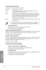
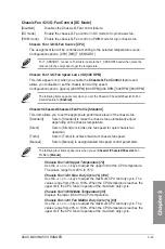
Fast Boot [Enabled]
[Disabled]
Allows your system to go back to its normal boot speed.
[Enabled]
Allows your system to accelerate the boot speed.
The following items appear only when you set the Fast Boot to
[Enabled]
.
SATA Support [All Devices]
[All Devices]
All devices connected to SATA ports are available during POST.
This process extends the POST time.
[Hard Drive Only] Only hard drives connected to SATA ports are detected during
POST.
[Boot Drive Only]
Only boot drives connected to a SATA ports are detected during
POST.
USB Support [Partial Initialization]
[Disabled]
All USB devices will not be available until OS boot up for a
fastest POST time.
[Full Initialization] All USB devices will be available during POST. This process will
extend the POST time.
[Partial
Initialization]
For a faster POST time, only USB ports with keyboard and
mouse connections will be detected.
PS/2 Keyboard and Mouse Support [Auto]
Allows you to disable or have full system control of the PS/2 devices’ availability during
POST. Configuration options: [Auto] [Disabled] [Full Initialization]
Network Stack Driver Support [Disabled]
[Disabled] Select to skip the network stack driver from loading during POST.
[Enabled] Select to load the network stack driver during POST.
Next Boot after AC Power Loss [Normal Boot]
[Normal Boot] Returns to normal boot on the next boot after an AC power loss.
[Fast Boot] Accelerates the boot speed on the next boot after an AC power loss.
DirectKey (DRCT) [Enabled]
[Enabled]
Allow the system to turn on and go to the BIOS setup directly when the
reset button is pressed.
[Disabled]
The system will only turn on or off when the reset button is pressed.
You have to connect the 2-pin connector of the chassis reset button cable on the onboard
DRCT header to support this function.
Summary of Contents for Maximus VII Ranger
Page 1: ...Motherboard MAXIMUS VII RANGER ...
Page 62: ...1 48 Chapter 1 Product introduction Chapter 1 ...
Page 67: ...ASUS MAXIMUS VII RANGER 2 5 Chapter 2 To uninstall the CPU heatsink and fan assembly ...
Page 68: ...2 6 Chapter 2 Basic Installation Chapter 2 1 2 3 To remove a DIMM 2 1 4 DIMM installation B A ...
Page 69: ...ASUS MAXIMUS VII RANGER 2 7 Chapter 2 2 1 5 ATX Power connection 1 2 OR ...
Page 70: ...2 8 Chapter 2 Basic Installation Chapter 2 2 1 6 SATA device connection 2 OR 1 ...
Page 78: ...2 16 Chapter 2 Basic Installation Chapter 2 Connect to 7 1 channel Speakers ...
Page 80: ...2 18 Chapter 2 Basic Installation Chapter 2 ...
Page 142: ...3 62 Chapter 3 BIOS setup Chapter 3 ...
Page 176: ...4 34 Chapter 4 Software support Chapter 4 Function Keys Shortcut ...
Page 186: ...4 44 Chapter 4 Software support Chapter 4 ...
Page 200: ...A 6 Appendices Appendices ...


