background image

R

P2B-L / P2B-S / P2B-LS

Pentium

®

 II Motherboards

USER’S MANUAL

Special Features

ASUS P2B-L (power supply must provide at least 720mA on the +5VSB)

•  Intel 82558 LAN Chipset
•  Wake-On-LAN

ASUS P2B-S

•  Adaptec 7890 SCSI Chipset
•  Adaptec 3860 SCSI Transceiver

ASUS P2B-LS (power supply must provide at least 720mA on the +5VSB)

•  Intel 82558 LAN Chipset
•  Wake-On-LAN
•  Adaptec 7890 SCSI Chipset
•  Adaptec 3860 SCSI Transceiver

Summary of Contents for P2B-L

Page 1: ... must provide at least 720mA on the 5VSB Intel 82558 LAN Chipset Wake On LAN ASUS P2B S Adaptec 7890 SCSI Chipset Adaptec 3860 SCSI Transceiver ASUS P2B LS power supply must provide at least 720mA on the 5VSB Intel 82558 LAN Chipset Wake On LAN Adaptec 7890 SCSI Chipset Adaptec 3860 SCSI Transceiver ...

Page 2: ...ames appearing in this manual may or may not be registered trade marks or copyrights of their respective companies and are used only for identification or explanation and to the owners benefit without intent to infringe Intel LANDesk and Pentium are registered trademarks of Intel Corporation IBM and OS 2 are registered trademarks of International Business Machines Symbios is a registered trademark...

Page 3: ...TERNATIONAL Marketing Address 6737 Mowry Avenue Mowry Business Center Building 2 Newark CA 94560 USA Fax 1 510 608 4555 Email info usa asus com tw Technical Support Fax 1 510 608 4555 BBS 1 510 739 3774 Email tsd usa asus com tw WWW www asus com FTP ftp asus com tw pub ASUS ASUS COMPUTER GmbH Marketing Address Harkort Str 25 40880 Ratingen BRD Germany Telephone 49 2102 445011 Fax 49 2102 442066 Em...

Page 4: ...nk 23 4 Expansion Cards 24 Expansion Card Installation Procedure 24 Assigning IRQs for Expansion Cards 24 Assigning DMA Channels for ISA Cards 25 ISA Cards and Hardware Monitor 25 Accelerated Graphics Port 25 5 External Connectors 26 Power Connection Procedures 35 IV BIOS SOFTWARE Main Menu 36 Flash Memory Writer Utility 36 Managing and Updating Your Motherboard s BIOS 38 6 BIOS Setup 39 Load Defa...

Page 5: ...ace DMI 60 VII NETWORK INTERFACE Features 63 Software Driver Support 63 LED Connectors 64 DOS and Windows 3 1 Setup for Novell 65 Windows NT Server or Workstation 66 Windows 95 68 Select Duplex Mode optional 69 Troubleshooting 71 Technical Information 74 Using Wake On LAN 75 Glossary 76 VIII ADAPTEC SCSI SELECT Configuring the SCSI Adapter 77 SCSI Disk Utilities 77 IX ADAPTEC EZ SCSI UTILITY Quick...

Page 6: ...articular installation If this equipment does cause harmful interference to radio or television reception which can be determined by turning the equipment off and on the user is encouraged to try to correct the inter ference by one or more of the following measures Re orient or relocate the receiving antenna Increase the separation between the equipment and receiver Connect the equipment to an out...

Page 7: ...III Adaptec SCSI Select Adaptec SCSI Select utility optional IX Adaptec EZ SCSI Adaptec EZ SCSI utility optional Item Checklist Check that your package is complete If you discover damaged or missing items contact your retailer 1 ASUS Motherboard 1 Retention mechanism heatsink support for CPU and heatsink 2 Attach mount bridges 1 IDE ribbon cable for master and slave drives 1 Floppy ribbon cable fo...

Page 8: ......

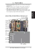
Page 9: ...ace Desktop Management Interface DMI Supports DMI through BIOS which allows hardware to communicate within a standard protocol creating a higher level of compatibility Requires DMI enabled components T USB Port 1 B USB Port 2 COM 2 Bottom Programmable 2Mbit Flash ROM 4PCI Slots Accelerated Graphics Port 2 ISA Slots T PS 2 Mouse B PS 2 Keyboard Parallel Top Serial Bottom Intel 440BX AGPset Hardware...

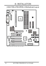
Page 10: ...et 0 64 72 bit 168 pin module DIMM Socket 1 64 72 bit 168 pin module 50 Pin SCSI 68 Pin Ultra2 SCSI 68 34 1 35 Adaptec SCSI Chipset Intel 82558 Ethernet LAN Controller Mouse top port Keyboard bottom port USB PS 2 RJ 45 BIOS Power CR2032 3V Lithium Cell PANEL IR KBPWR USB 1 top port USB 2 bottom port BUS Freq FS1 FS2 FS0 CHASSIS EXTBATT Freq Ratio BF3 BF2 BF1 BF0 ASUS A97127F Chipset SCSILED Multi ...

Page 11: ... RJ 45 Connector 8 pin female 6 USB p 28 Universal Serial BUS Ports 1 2 two 4 pin female 7 A p 28 LAN Condition Connector 6 pins 8 FLOPPY p 28 Floppy Drive Connector 34 1 pins 9 Primary Secondary IDE p 29 Primary Secondary IDE Connector 40 pins 10 IDELED SCSILED p 29 IDE SCSI LED Activity Light two 2 pins 11 SCSI 50 SCSI 68 ULTRA2 68 p 30 Ultra Fast 50 Wide 68 Ultra2 68 SCSI Connectors 12 IR p 31 ...

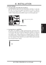
Page 12: ... On and for Open Off For manufacturing simplicity the jumpers may be sharing pins from other groups Use the diagrams in this manual instead of following the pin layout on the board Set tings with two jumper numbers require that both jumpers be moved together To connect the pins simply place a plastic jumper cap over the two pins as diagrammed WARNING Computer motherboards baseboards and components...

Page 13: ... preferences Short the solder points to clear CMOS P2B L S LS Real Time Clock RAM CLRTC CLRTC R 2 Keyboard Power Up KBPWR This allows you to disable or enable the keyboard power up function Set to Enable if you want to use your keyboard by pressing Spacebar to power up your computer This feature requires an ATX power supply that can supply at least 300mAon the 5VSB lead and the newACPI BIOS suppor...

Page 14: ...abled using this jumper R P2B L S LS Onboard SCSI Setting Enable Default Disable SCSI_EN SCSI_EN 1 2 3 1 2 3 5 IDE SCSI Device Activity LED Selection COMBINE The IDE and SCSI Activity LEDs normally has separate connections If you have both SCSI and IDE devices connected to this motherboard but only have one LED on your system cabinet place a jumper on COMBINE in order to combine the IDE and SCSI a...

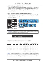
Page 15: ...set in conjunction with the CPU Bus Frequency WARNING Frequencies above 100Mhz exceed the specifications for the on board Intel Chipset and are not guaranteed to be stable Set the jumpers by the Internal speed of your processor as follows BUS Freq Freq Ratio CPU Model Freq Ratio BUS F FS2 FS1 FS0 BF3 BF2 BF1 BF0 Intel Pentium II 450MHz 4 5x 100MHz 1 2 1 2 1 2 2 3 1 2 2 3 1 2 Intel Pentium II 400MH...

Page 16: ...16 ASUS P2B L P2B S P2B LS User s Manual This page was intentionally left blank ...

Page 17: ...y General DIMM Notes Use only PC100 compliant DIMMs This motherboard operates at 100MHz thus most systems will not even boot if non compliant modules are used be cause of the strict timing issues involved under this speed Two possible memory chips are supported SDRAM with and without ECC SDRAM chips are generally thinner with higher pin density than traditional EDO Extended Data Output chips BIOS ...

Page 18: ...pin density R Lock P2B L S LS 168 Pin DIMM Memory Sockets FRONT 88 Pins 60 Pins 20 Pins The DIMMs must be 3 3Volt unbuffered SDRAMs To determine the DIMM type check the notches on the DIMMs see figure below 168 Pin DIMM Notch Key Definitions 3 3V DRAM Key Position Voltage Key Position Unbuffered RFU Buffered Reserved 3 3V 5 0V The notches on the DIMM will shift between left center or right to iden...

Page 19: ...on the processor could overheat and damage both the processor and the motherboard You may install an auxiliary fan if necessary You should check to see that you have the following 9 items NOTE The pictures in the following pages will have the same item numbers next to them for your reference The design and color of your items may be slightly different Attach Mount Bridges Items 1 2 1 2 Pentium II ...

Page 20: ...ient the mechanism s lock holes toward the motherboard s chipset see moth erboard layout for the location of the AGPset Be sure to align the notch in the mechanism with the small rib on one side of the slot and that the mechanism is properly seated on the board Then screw the captive nuts in place WARNING Do not overtighten the captive nuts Doing so could damage your motherboard Tighten captive nu...

Page 21: ...must be showing through between the thermal pad of the heatsink and the SEC cartridge WARNING If the heatsink is not mounted tightly against the SEC cartridge the CPU will overheat You may install an auxiliary fan to provide adequate circulation across the processor s passive heatsink SEC Cartridge with Heatsink Side View SEC Cartridge with Heatsink Top View Push each end of the clamps until they ...

Page 22: ...nk with fan see next page The support base is necessary to secure the heatsink without fan Secure the heatsink by sliding the heatsink support top bar into the bottom groove of the heatsink until it locks into the heatsink support base posts Heatsink support base 7 6 Connect the Heat Sensor Cable to TRCPU optional If you purchased the specially designed fan and thermal monitor heatsink you can con...

Page 23: ...s that for the heatsink without a fan You will not however be able to use the heatsink support top bar because of the fan The heatsink support top bar will however still be included in the package in case you use a heatsink without a fan Elan Vital Heatsink TheproceduresforinstallingtheElanVitalheatsinkwithfanisalsosimilartothesteps for installing the heatsink without a fan The Elan Vital heatsink...

Page 24: ...use an IRQ to operate Generally an IRQ must be exclusively assigned to one use In a standard design there are 16 IRQs available but most of them are already in use leaving 6 IRQs free for expansion cards If your motherboard has audio onboard an extra 3 IRQs will be used leaving 3 IRQs free Both ISA and PCI expansion cards may require to use IRQs System IRQs are avail able to cards installed in the...

Page 25: ...ard you need to set the INT interrupt assignment Since all the PCI slots on this mother board use an INTA set the jumpers on your PCI cards to INT A Assigning DMA Channels for ISA Cards Some ISAcards both legacy and PnP may also need to use a DMA Direct Memory Access channel DMA assignments for this motherboard are handled the same way as the IRQ assignment process described earlier You can select...

Page 26: ...loppy drives IDE ribbon cable must be less than 46cm 18in with the second drive connector no more than 15cm 6in from the first connector 1 PS 2 Keyboard Connector 6 pin Female This connection is for a standard keyboard using a PS 2 plug mini DIN This connector will not allow standard AT size large DIN keyboard plugs You may use a DIN to mini DIN adapter on standard AT keyboards P2B L S LS PS 2 Key...

Page 27: ...P2B L S LS Parallel Port 25 pin Female 4 Serial Port COM1 and COM2 Connectors Two 9 pin Male The two serial ports can be used for pointing devices or other serial devices See Onboard Serial Port in Chipset Features Setup of the BIOS SOFTWARE P2B L S LS Serial Ports 9 pin Male COM 1 COM 2 5 RJ 45 Connector 8 pin Female This connector can be used to connect the onboard 32 bit 10 100 Mbps Ethernet LA...

Page 28: ... to system cases that support this feature R P2B L S LS Network Condition LED Connectors Link LED Connector Activity LED Connector Speed LED Connector 8 Floppy Disk Drive Connector 34 1pin FLOPPY This connector supports the provided floppy disk drive ribbon cable After con necting the single end to the board connect the two plugs on the other end to the floppy drives Pin 5 is removed to prevent in...

Page 29: ...se refer to the docu mentation of your hard disk for the jumper settings BIOS now supports SCSI device or IDE CD ROM bootup see HDD Sequence SCSI IDE First Boot Sequence in the BIOS Features Setup of the BIOS SOFTWARE Pin 20 is removed to prevent inserting in the wrong orientation when using ribbon cables with pin 20 plugged TIP You may configure two hard disks to be both Masters using one ribbon ...

Page 30: ...2 devices With Ultra2 devices the SCSI bus platform performs at full Ultra2 speeds up to 40 MB sec in 8 bit mode and up to 80 MB sec in 16 bit mode and extended cabling 12m or 25m in a point to point configuration When an SE device is attached the bus defaults to an SE speed and cable length InmixedenvironmentsofUltra2andSEdevices theonboardhostadaptercanbecoupledwiththe AdaptecAIC 3860 transceive...

Page 31: ...cable from the module to the motherboard according to the pin definitions R Front View P2B L S LS Infrared Module Connector For the infrared feature to be available you must connect the optional Infrared IrDA module to the motherboard 5V IRRX IRTX NC GND 5V IRTX IRRX NC GND Back View 13 SB LINK Connector 6 1 pin SBLINK Using Intel s PC PCI technology this connector allows Sound Blaster 16 com pati...

Page 32: ......

Page 33: ...ion signal is to be used only with a specially designed fan with rotation signal WARNING The CPU and or motherboard will overheat if there is no airflow across the CPU and onboard heatsinks Damage may occur to the motherboard and or the CPU fan if these pins are incorrectly used These are not jumpers do not place jumper caps over these pins R P2B L S LS 12Volt Cooling Fan Power Power Supply Fan Po...

Page 34: ... pins are aligned R P2B L S LS ATX Power Connector 3 3Volts 12 0Volts Ground PWR Supply On Ground Ground Ground 5 0 Volts 5 0 Volts 5 0 Volts Power Good 12 0Volts 3 3 Volts 3 3 Volts Ground 5 0 Volts Ground 5 0 Volts Ground 5V Standby IMPORTANT Make sure that yourATX power supply can supply at least 10mA on the 5 volt standby lead 5VSB For motherboards with the onboard LAN chipset your ATX power s...

Page 35: ...onitor LED may light up after the system s if it complies with green stan dards or if it has a power standby feature The system will then run power on tests While the tests are running additional messages will appear on the screen If you do not see anything within 30 seconds from the time you turn on the power the system may have failed a power on test Recheck your jumper set tings and connections...

Page 36: ...reen displays are provided as examples only and may not reflect the screen contents displayed on your system Main Menu 1 Save Current BIOS To File This option allows you to save a copy of the original motherboard BIOS in case you need to reinstall it It is recommended that you save AFLASH EXE and the BIOS file to a bootable floppy disk To save your current BIOS type 1 at the Main Menu and then pre...

Page 37: ...r block from a new BIOS file See the next page for procedures on downloading an updated BIOS file The utility starts to program the new BIOS information into the flash ROM When the programming is finished Flashed Successfully will be displayed To update your current BIOS type 2 at the Main Menu and then press Enter The Update BIOS Including Boot Block and ESCD screen appears Type the filename of y...

Page 38: ...t WWW or FTP or a BBS Bulletin Board Service seeASUS CONTACT INFORMATION on page 3 for details and save to the disk you created earlier 2 Boot from the disk you created earlier 3 At the A prompt type AFLASH and then press Enter 4 At the Main Menu type 2 and then press Enter See 2 Update BIOS In cluding Boot Block and ESCD on the previous page for more details and the rest of the steps WARNING If y...

Page 39: ...s If you are installing the motherboard reconfiguring your system or you receive a Run Setup message you will need to enter new setup information This section describes how to configure your system using this utility The BIOS ROM of the system stores the Setup utility When you turn on the com puter the system provides you with the opportunity to run this program This ap pears during the Power On S...

Page 40: ...ption anymore However if the configuration stored in the CMOS memory on the board gets lost or damaged or if you change your system hardware configuration you will need to respecify the configuration values The configuration values usually get lost or corrupted when the power of the onboard CMOS battery weakens The preceding screen provides you with a list of options At the bottom of this screen a...

Page 41: ...ive documentations on how to install the re quired SCSI drivers For IDE hard disk drive setup you can Use the Auto setting for detection during bootup Use the IDE HDD AUTO DETECTION in the main menu to automatically enter the drive specifications Enter the specifications yourself manually by using the User option The entries for specifying the hard disk type include CYLS number of cylinders HEAD n...

Page 42: ... possible with FDISK NOTE SETUP Defaults are noted in parenthesis next to each function heading Drive A Drive B None These fields record the types of floppy disk drives installed in your system The available options for drives A and B are 360KB 5 25 in 1 2MB 5 25 in 720KB 3 5 in 1 44MB 3 5 in 2 88MB 3 5 in None To enter the configuration value for a particular drive highlight its corresponding fie...

Page 43: ...esis next to each function heading Details of BIOS Features Setup CPU Internal Core Speed This function is reserved for future use and is currently disabled Boot Virus Detection Enabled This field allows you to set boot virus detection ensuring a virus free boot sector This new antivirus solution is unlike native BIOS tools which offer limited virus protection typically by write protecting the par...

Page 44: ...k when set to SCSI This allows multiple operating systems to be used on both IDE and SCSI drives or the primary operating system to boot using a SCSI hard disk drive Boot Sequence A C This field determines where the system looks first for an operating system Options are A C A CDROM C CDROM C A D A E A F A C only LS ZIP C and C A The setup default setting A C is to check first the floppy disk and t...

Page 45: ...ese fields are used for shadowing other expansion card ROMs If you install other expansion cards with ROMs on them you will need to know which addresses the ROMs use to shadow them specifically Shadowing a ROM reduces the memory available between 640K and 1024K by the amount used for this purpose Boot Up NumLock Status On This field enables users to activate the Number Lock function upon system bo...

Page 46: ......

Page 47: ...o 16MB memory address space to ISA expan sion cards that specifically require this setting This makes the memory from 15MB and up unavailable to the system Expansion cards can only access memory up to 16MB The default is Disabled DRAM are xx bits wide If all your DIMMs have ECC chips e g 8 chips 1 ECC chip they are considered 72bits and the following will be displayed If your DIMMs do not have ECC...

Page 48: ...han the maximum unidirectional data transfer rate ECP EPP allows normal speed operation in a two way mode ECP DMA Select 3 This selection is available only if you select ECP or ECP EPP in the Parallel Port Mode Select either DMA Channel 1 3 or Disable UART2 Use Infrared Disabled When enabled this field activates the onboard infrared feature and sets the second serial UART to support the infrared m...

Page 49: ...aving except that this time the system inac tivity period is longer Disable disables the power saving features User Define al lows you to set power saving options according to your preference IMPORTANT Advanced Power Management APM should be installed to keep the system time updated when the computer enters suspend mode activated by the BIOS Power Management For DOS environments you need to add th...

Page 50: ... activity detected from the enabled IRQ channels HDD Power Down Disable Shuts down any IDE hard disk drives in the system after a period of inactivity This time period is user configurable to 1 15 Min or Disable This feature does not affect SCSI hard drives Suspend Mode Disable Sets the period of time after which each of these modes activate 30 sec 1 Min 2 Min 4 Min 8 Min 20 Min 30 Min 40 Min 1 Ho...

Page 51: ...ptional network interface see VII Net work Interface and anATX power supply with at least 720mA 5V standby power Automatic Power Up Disabled This allows you to have an unattended or automatic power up of your system You may configure your system to power up at a certain time of the day by selecting Everyday which will allow you to set the time or at a certain time and day by selecting By Date Fan ...

Page 52: ... set how IRQ use is determined for each PCI slot The default setting for each field is Auto which uses auto routing to determine IRQ use The other options are manual settings of NA 5 7 9 10 11 12 14 or 15 for each slot PCI Latency Timer 32 PCI Clock The default setting of 32 PCI Clock enables maximum PCI performance for this motherboard IRQ xx Used By ISA No ICU These fields indicate whether or no...

Page 53: ... AHA BIOS Auto The default uses Auto settings for the onboardAdaptec 7890 SCSI BIOS If you do not want to use the onboard Adaptec 7890 SCSI BIOS choose Disabled ONB AHA BIOS First No This field allows giving priority to the onboard SCSI BIOS for SCSI functions over other SCSI controllers The default is No ONB SCSI SE Term Enabled This allows you to enable or disable the onboard termination for sin...

Page 54: ...the screen Press Y and then Enter to confirm Press N and then Enter to abort This feature does not affect the fields on the Standard CMOS Setup screen Load Setup Defaults The Load Setup Defaults option allows you to load the default values to the sys tem configuration fields These default values are the optimized configuration set tings for the system To load these default values highlight Load Se...

Page 55: ...s case sensitive and can be up to 8 alphanumeric characters long type in your password and then press Enter The system confirms your password by asking you to type it again After setting a password the screen automatically re verts to the main screen To implement password protection specify in the Security Option field of the BIOS Features Setup screen when the system will prompt for the password ...

Page 56: ...ature En hanced IDE support for four devices you can only install two IDE hard disk drives Your IDE controller must support the Enhanced IDE features in order to use Drive E and Drive F The onboard PCI IDE controller supports Enhanced IDE with two connectors for connecting up to four IDE devices If you want to use another con troller that supports four drives you must disable the onboard IDE contr...

Page 57: ...s that should be used for your disk do not accept them Press N to reject the presented settings and enter the correct ones manually from the Standard CMOS Setup screen Save Exit Setup Select this option to save into the CMOS memory all modifications you specified during the current session To save the configuration changes highlight the Save Exit Setup option on the main screen type Y and then pre...

Page 58: ...herbaord Support CD Main Menu Insert the support CD or double click on your CD drive icon in My Computer to bring up the autorun menu or run Setup exe in the root directory of the Support CD NOTE The support CD contents are constantly updated without notice V Support CD ...

Page 59: ...y to view the user s manuals in Adobe Acrobat PDF format BusMaster BUSMASTR Installs the Intel BusMaster IDE drivers for improved performance Install AdaptecAIC 7890 Driver SCSI Click for instructions on installing the Adaptec SCSI drivers for your system Various drivers are provided in the SCSI directory Patch for PIIX4 chipset PX4PATCH Installs the necessary drivers for PCI card and PCI bridge f...

Page 60: ...s creating a new BIOS image file and requiring the user to update the whole BIOS This DMI Con figuration Utility also allows the system integrator or end user to add additional information into the MIFD such as serial numbers housing configurations and ven dor information Those information not detected by the motherboard BIOS and has to be manually entered through the DMI Configuration Utility and...

Page 61: ...ilable for editing The orange text shows auto detected information and are not available for editing The blue text Press ENTER for detail contains a second pop up menu is available use the plus minus keys to change the settings Enter to exit and save ESC to exit and not save If the user has made changes ESC will prompt you to answer Y or N Enter Y to go back to the left hand screen and save enter ...

Page 62: ...ss ESC and a message Bad File Name appears here to show it was not saved Load MIFD You can load the disk file to memory by entering a drive and path and file name here Load BIOS Defaults You can load the BIOS defaults from a MIFD file and can clear all user modified and added data You must reboot your computer in order for the defaults to be saved back into the Flash BIOS VI DMI Utility Using DMI ...

Page 63: ...es Complies to IEEE 802 3 10BASE T and IEEE 802 3U 100BASE TX interfaces Fully supports 10BASE T 100BASE TX operations Single RJ 45 Connector Auto Detection of 10Mbps or 100Mbps Network Data Transfer Rates and Connected Cable Types 32 bit Bus Master Technology PCI Rev 2 1 Plug and Play Enhancements on ACPI APM Adheres to PCI Bus Power Management Interface Rev 1 0 ACPI Rev 1 0 and Device Class Powe...

Page 64: ...E Connect a single network cable to the RJ45 connector For 100BASE TX your network cable must be category 5 not category 3 twisted pair wiring with RJ45 connectors If you plan on running the interface at 100 Mbps it must be connected to a 100BASE TX hub not a 100BASE T4 hub For 10BASE T use category 3 4 or 5 twisted pair wiring Twisted Pair Cable The cable used to connect the Ethernet card to a ho...

Page 65: ...oaded from the AUTOEXEC BAT or CONFIG SYS file type REM in front of each line that loads a network driver Or with DOS 6 x or later press F5 as DOS starts to bypass the drivers 2 Insert the ASUS Configuration and Drivers disk in a floppy drive switch to that drive and at the DOS prompt type SETUP 3 If you have another network adapter in your computer an adapter selection menu appears on the screen ...

Page 66: ...y if you have a responder on the network while running the tests 1 Go to a computer on the network with any EtherExpress adapter or interface in stalled except EtherExpress 32 or EtherExpress 16 MCA 2 Run the appropriate configuration program for the installed interface and set it up as a responder 3 Return to the computer with the new adapter or interface Run Setup and make the new interface the ...

Page 67: ... Other Requires disk from manufacturer 4 Insert the ASUS Configuration and Drivers disk in the A drive and click OK 5 Select the Intel EtherExpress PRO Adapter and click OK 6 Click OK in the Network Settings dialog box and remove the installation disk When prompted restart Windows NT To install multiple network interface or adapters repeat this procedure for each new network interface or adapter T...

Page 68: ...m Disk dialog box appears 3 Insert the ASUS Configuration and Drivers disk 4 Specify A or B as the path then click OK 5 Follow prompts for any Windows 95 installation disks and restart when prompted If you installed from CD ROM the installation files are typically located at D Win95 where D is your CD ROM drive After restartingWindows 95 you should be able to connect to your network by double clic...

Page 69: ...etwork interface or adapter duplex mode manually see following paragraphs Half duplex The network interface or adapter performs one operation at a time it either sends or receives NOTE If your hub is running at 100 Mbps and half duplex your potential bandwidth is higher than if you run at 10 Mbps and full duplex Manually Configuring for Full Duplex If your switch supports auto negotiation with the...

Page 70: ...dow If you have multiple adapters click the adapter you are configuring you can identify it by its Ethernet address Each adapter must be configured separately 3 From the window that appears click Change 4 From the Adapter Setup window click the menu for Network Speed 5 Click 100 or 10 Mbps depending on hub speed 6 Click the menu for Duplex Mode 7 Click Full 8 Click OK when finished 9 Click OK to r...

Page 71: ...onnector cable or hub The table below describes the LEDs LED Indication Meaning LNK On The interface and hub have acknowledged a connection the link between the hub and interface is good Off The cable connection between the hub and interface is faulty or you have a driver configuration problem ACT On or flashing The interface is sending or receiving network data The freq uency of the flashes varie...

Page 72: ...wiring and make sure the network cable is securely attached For NetWare clients make sure you specify the correct frame type in the NET CFG file Make sure the duplex mode setting on the network interface or adapter matches the setting on the hub At 100 Mbps connect to a 100BASE TX hub only not T4 The LNK LED doesn t light Make sure you ve loaded the network drivers Check all connections at the net...

Page 73: ... interface stopped working without apparent cause Try reconnecting the cable to the RJ45 port first The network driver files may be corrupt or deleted Delete and then reinstall the drivers Try another motherboard of the same model Run the diagnostics The Wake On LAN feature is not working Make sure the WOL cable is attached and power is applied to the computer Check the BIOS for its WOL setting So...

Page 74: ...vehicles on the highway increases the traffic becomes con gested and tran sit time increases for individual cars On a shared hub all nodes must operate at the same speed either 10 Mbps or 100 Mbps Fast Ethernet repeaters provide 100 Mbps of available bandwidth ten times more than what s available with a 10BASE T repeater Repeaters use a well established uncomplicated design making them highly cost...

Page 75: ...ter to power up and run a pre defined program Question and Answer Q What is Wake On LAN A The Wake On LAN feature provides the capability to remotely power on systems supporting Wake On LAN by simply sending a wake up frame With this feature remotely uploading downloading data to from systems during off peak hours will be feasible Q What can Wake On LAN do for you A Wake On LAN is a remote managem...

Page 76: ...mmunicate with LAN cards or other network interfaces Driver A program that enables the network operating system to communicate with LAN cards IEEE 802 3 standard Standard for the physical and electrical connections in local area networks devel oped by the IEEE Institute of Electrical and Electronics Engineers IEEE 802 3u standard IEEE standard for LocalArea Networks LAN employing CSMA CD as the ac...

Page 77: ...on SCSI IDs 0 though 15 listing all devices on the bus including non disk devices When you select a device from the list and press Enter key another window appears giving you the option of selecting one of two sub utilities Format Disk or Verify Media These utilities are used for hard disk drives only and will have no effect on other non disk SCSI devices Format Disk low level formats your SCSI ha...

Page 78: ...78 ASUS P2B L P2B S P2B LS User s Manual This page was intentionally left blank ...

Page 79: ...uter system you may not be able to access your SCSI CDROM drive at first Usually you install Windows95 andWindowsNTfrom a CDROM disc To gain access to your CDROM drive follow the DOS Quick Start instructions below Windows Windows for Workgroups 3 1x 1 Install Windows 3 1x or Windows for Workgroups 3 1x and start it running on your computer 2 Insert the Adaptec EZSCSI Setup Disk into your floppy di...

Page 80: ...dowsNT to control host adapters and other kinds of devices Win dows95 and WindowsNT include a set of miniport drivers for various types of SCSI host adapters The host adapter miniport driver is automatically installed and con figured during Windows95 and WindowsNT installation if your host adapter is al ready installed To make sure the driver is installed correctly in systems running Windows95 ope...

Page 81: ...us question answer If a yellow exclamation point appears in front of your host adapter name the resources that the driver uses probably do not match the resources used by the hardware Double click the host adapter name then click on the Resource tab Deselect the Use automatic settings box and edit the resources Interrupt Request Direct Memory Access etc so they match those used by the host adapter...

Page 82: ...elect Re start the computer in MS DOS mode When the DOS prompt appears follow the Quick Start instructions for DOS My CDROM drive doesn t work properly under Windows95 Some older models of SCSI CDROM drives are not compatible with the embedded Windows95 CDROM driver You can add support for the CDROM drive by doing the following 1 Click the Start button and select Restart the computer in MS DOS mod...

Page 83: ...d lines to your CONFIG SYS and AUTOEXEC BAT files to load these device drivers if it finds these kinds of devices on your computer To learn more about the Adaptec EZSCSI device drivers including their command line option information see the online Adaptec EZSCSI Online Reference a Win dows Help application DOS and Windows3 1x ASPI Managers ASPI Advanced SCSI Programming Interface managers are soft...

Page 84: ...t screen appears read it and press Enter to continue Press F1 at any time to view Help Information about your SCSI disk devices appears on the screen 3 Use the arrow keys to move the highlight bar to a disk device you want to format or verify then press Enter 4 When the next screen appears select either Format or Verify to verify that the disk is free of surface defects then press Enter WARNING Ba...

Page 85: ...o the host adapter and that they are powered Then follow these steps 1 Change to the directory where afdisk exe is located usually c scsi type afdisk at the DOS prompt and press Enter Information about your SCSI disk devices appears on the screen The number that appears after Target is the device s SCSI ID 2 Use the arrow keys to move the highlight bar to the disk device you want to partition then...

Page 86: ... the numbers you want Partitions up to 2Gigabytes are supported 5 When the number of cylinders is what you want press Esc When the confir mation prompt appears select Yes and press Enter to create the partition To create more partitions on the same disk device repeat steps 3 4 and 5 As you create partitions on the disk they are added to the window at the upper right of the screen as shown here Sel...

Page 87: ...ASUS P2B L P2B S P2B LS User s Manual 87 This page was intentionally left blank ...

Page 88: ...88 ASUS P2B L P2B S P2B LS User s Manual This page was intentionally left blank ...

Reviews: