
5-26
Chapter 5: BIOS setup
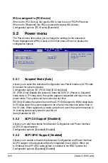
5.4.5
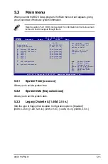
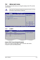
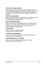
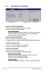
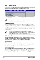
Onboard Devices Configuration
Configure Win627DHG-A Super IO Chipset
Onboard PCIE GbE LAN
[Enabled]
LAN Option ROM
[Disabled]
Serial Port1 Address
[3F8/IRQ4]
Parallel Port Address
[378]
Parallel Port Mode
[ECP]
ECP Mode DMA Channel
[DMA3]
Parallel Port IRQ
[IRQ7]
Onboard PCIE GbE LAN [Enabled]
Allows you to enable or disable the onboard LAN controller.
Configuration options: [Enabled] [Disabled]
LAN Option ROM [Disabled]
Allows you to enable or disable the boot ROM in the onboard LAN controller.
This item appears only when the Onboard LAN item is set to Enabled.
Configuration options: [Disabled] [Enabled]
Serial Port1 Address [3F8/IRQ4]
Allows you to select the Serial Port1 base address.
Configuration options: [Disabled] [3F8/IRQ4] [2F8/IRQ3] [3E8/IRQ4] [2E8/IRQ3]
Parallel Port Address [378]
Allows you to select the Parallel Port base addresses.
Configuration options: [Disabled] [378] [278] [3BC]
Parallel Port Mode [ECP]
Allows you to select the Parallel Port mode.
Configuration options: [Normal] [Bi-Directional] [EPP] [ECP]
ECP Mode DMA Channel [DMA3]
Appears only when the Parallel Port Mode is set to [ECP]. This item
allows you to set the Parallel Port ECP DMA.
Configuration options: [DMA0] [DMA1] [DMA3]
Parallel Port IRQ [IRQ7]
Allows you to select parallel port IRQ. Configuration options: [IRQ5] [IRQ7]
Onboard PCIEX GBE LAN_
Enable/Disable
Summary of Contents for P3-P5G31
Page 52: ...3 Chapter 3 Getting started ...


