4-8
Chapter 4: Motherboard info
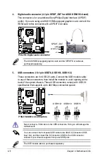
4. Digital audio connector (4-1 pin SPDIF_OUT for ASUS HDMI VGA card)
This connector is for an additional Sony/Philips Digital Interface (S/PDIF)
port(s). If you are using an ASUS HDMI-equipped graphics card, connect the
HDMI card to this connector with a S/PDIF Out cable.
The ASUS HDMI-equipped graphics card and the S/PDIF Out cable are
purchased separately.
P5K-VM
®
P5K-VM Digital audio connector
+5V
SPDIFOUT
GND
SPDIF_OUT
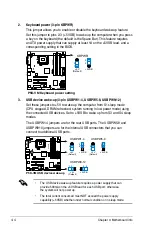
5. USB connectors (10-1 pin USB78, USB 910, USB1112)
These connectors are for USB 2.0 ports. Connect the USB module cable
to any of these connectors, then install the module to a slot opening at the
back of the system chassis. These USB connectors comply with USB 2.0
specification that supports up to 480 Mbps connection speed.
Never connect a 1394 cable to the USB connectors. Doing so will damage the
motherboard!
P5K-VM
®
P5K-VM USB 2.0 connectors
USB1112
NC
GND
USB_P12-
USB+5V
GND
USB_P1
1+
USB_P1
1-
USB+5V
pin1
USB910
NC
GND
USB_P10-
USB+5V
GND
USB_P9-
USB+5V
pin1
USB78
NC
GND
USB_P8-
USB+5V
GND
USB_P7-
USB+5V
pin1
You can connect the front panel USB cable to the ASUS Q-Connector (USB,
blue) first, and then install the Q-Connector (USB) to the USB connector
onboard if your chassis supports front panel USB ports.
The USB module cable is purchased separately.
Summary of Contents for P3-P5G33 - P Series - 0 MB RAM
Page 98: ...5 34 Chapter 5 BIOS setup ...

