background image

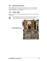
ASUS P4S800-X motherboard

1-21

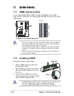
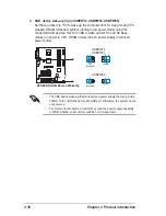
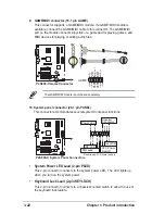
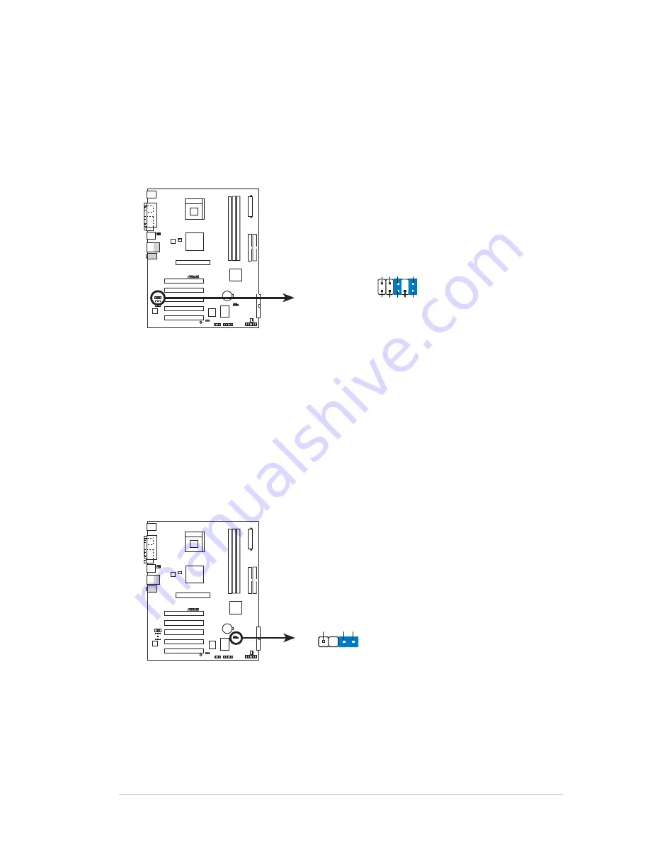
8. Chassis intrusion connector (4-1 pin CHASSIS)

This lead is for a chassis designed with intrusion detection feature. This
requires an external detection mechanism such as a chassis intrusion sensor
or microswitch. When you remove any chassis component, the sensor triggers
and sends a high-level signal to this lead to record a chassis intrusion event.

By default, the pins labeled “Chassis Signal” and “Ground” are shorted with a
jumper cap. If you wish to use the chassis intrusion detection feature, remove
the jumper cap from the pins.

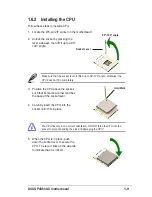
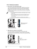
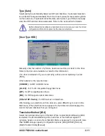
7. Front panel audio connector (10-1 pin FP_AUDIO)

This is an interface for the front panel cable that allows convenient connection
and control of audio devices.

Be default, the pins labeled LINE OUT_R/BLINE_OUT_R and the pins
LINE OUT_L/BLINE_OUT_L are shorted with jumper caps. Remove the caps
only when you are connecting the front panel audio cable.

P4S800-X

®

P4S800-X Front Panel Audio Connector

FP_AUDIO

BLINE_OUT_L

MIC2

Line out_R

Line out_L

BLINE_OUT_R

NC

MICPWR

+5V

A

AGND

P4S800-X

®

P4S800-X Chassis Alarm Lead

CHASSIS

+5VSB_MB

Chassis Signal

GND

(Default)

Summary of Contents for P4S800-X

Page 1: ...Motherboard P4S800 X User Guide ...

Page 2: ...A PARTICULAR PURPOSE IN NO EVENT SHALL ASUS ITS DIRECTORS OFFICERS EMPLOYEES OR AGENTS BE LIABLE FOR ANY INDIRECT SPECIAL INCIDENTAL OR CONSEQUENTIAL DAMAGES INCLUDING DAMAGES FOR LOSS OF PROFITS LOSS OF BUSINESS LOSS OF USE OR DATA INTERRUPTION OF BUSINESS AND THE LIKE EVEN IF ASUS HAS BEEN ADVISED OF THE POSSIBILITY OF SUCH DAMAGES ARISING FROM ANY DEFECT OR ERROR IN THIS MANUAL OR PRODUCT SPECI...

Page 3: ... overview 1 6 1 5 1 Motherboard layout 1 6 1 5 2 Placement direction 1 7 1 5 3 Screw holes 1 7 1 6 Central Processing Unit CPU 1 8 1 6 1 Overview 1 8 1 6 2 Installing the CPU 1 9 1 7 System memory 1 10 1 7 1 DIMM sockets location 1 10 1 7 2 Installing a DIMM 1 10 1 7 3 DIMM Qualified Vendors List 1 11 1 8 Expansion slots 1 12 1 8 1 Standard interrupt assignments 1 12 1 8 2 IRQ assignments for this...

Page 4: ...ary Master Slave 2 10 2 3 2 Keyboard Features 2 13 2 4 Advanced Menu 2 13 2 4 1 Chip Configuration 2 15 2 4 2 I O Device Configuration 2 17 2 4 3 PCI Configuration 2 18 2 5 Power Menu 2 20 2 5 1 Power Up Control 2 21 2 5 2 Hardware Monitor 2 22 2 6 Boot Menu 2 22 2 7 Exit Menu 2 24 Chapter 3 Software support 3 1 Install an operating system 3 2 3 2 Support CD information 3 2 3 2 1 Running the suppo...

Page 5: ...ian ICES 003 The use of shielded cables for connection of the monitor to the graphics card is required to assure compliance with FCC regulations Changes or modifications to this unit not expressly approved by the party responsible for compliance could void the user s authority to operate this equipment Where to find more information Refer to the following sources for additional information and for...

Page 6: ...your area If you are not sure about the voltage of the electrical outlet you are using contact your local power company If the power supply is broken do not try to fix it by yourself Contact a qualified service technician or your retailer Operation safety Before installing the motherboard and adding devices on it carefully read all the manuals that came with the package Before using the product ma...

Page 7: ...ask NOTE Tips and additional information to aid in completing a task Typography Bold text Indicates a menu or an item to select Italics Used to emphasize a word or a phrase Key Keys enclosed in the less than and greater than sign indicates that you must press the enclosed key Example Enter indicates that you must press the Enter or Return key Multiple key names If you must press two or more keys s...

Page 8: ...ith 32 DDR chips support to 1 DIMM only 1 x AGP 8X 1 5V only 5 x PCI 2 x Ultra DMA 133 100 66 33 connectors ADI AD1888 6 channel audio CODEC S PDIF out interface Integrated 10 100 Mbps LAN controller VIA VT6103 PHY Maximum of six 6 USB 2 0 ports ASUS EZ Flash ASUS Instant Music Lite ASUS CrashFree BIOS 2 ASUS JumperFree ASUS C P R CPU Parameter Recall CPU Memory and AGP Voltage adjustable SFS Step...

Page 9: ...E MIDI connector CD AUX audio connectors Front panel audio connector 2Mb Flash ROM ASUS JumperFree Award BIOS TCAV PnP DMI2 0 WfM2 0 SM BIOS2 3 ASUS EZ Flash ASUS CrashFree BIOS 2 ASUS C P R PCI 2 2 USB 2 0 WfM 2 0 DMI 2 0 WOL WOR by PME Chassis intrusion SM Bus ATX form factor 12 in x 9 6 in Device drivers ASUS PC Probe ASUS LiveUpdate Utility Trend Micro PC cillin anti virus software OEM version...

Page 10: ...x ...

Page 11: ...ter 1 This chapter describes the features of the motherboard It includes brief descriptions of the motherboard components and illustrations of the layout jumper settings and connectors Product introduction ...

Page 12: ...effective desktop platform solution Supporting up to 3GB of system memory with PC3200 2700 2100 1600 DDR SDRAM high resolution graphics via an AGP 8X slot USB 2 0 and 6 channel audio features the motherboard takes you ahead in the world of power computing Before you start installing the motherboard and hardware devices on it check the items in your package with the list below 1 2 Package contents ...

Page 13: ...ion that enables enhanced graphics performance with maximum bandwidth speeds of up to 2 12 GB s 6 USB 2 0 ports The motherboard implements the new Universal Serial Bus USB 2 0 specification extending the connection speed from 12 Mbps on USB 1 1 to a fast 480 Mbps on USB 2 0 supporting up to six USB 2 0 ports The higher bandwidth of USB 2 0 allows connection of devices such as high resolution video...

Page 14: ...iminates the need to open the system chassis and clear the RTC data Simply shut down and reboot the system and BIOS automatically restores the CPU previous setting for each parameter Instant Music Lite This unique feature allows you to playback audio CDs even without booting the system to Windows Just press the ASUS Instant Music special function keys and enjoy the music See details on pages 2 15 ...

Page 15: ...grounded antistatic pad or in the bag that came with the component 5 Before you install or remove any component ensure that the ATX power supply is switched off or the power cord is detached from the power supply Failure to do so may cause severe damage to the motherboard peripherals and or components Onboard LED The motherboard comes with a stand by power LED When lit this green LED indicates tha...

Page 16: ...ocket 478 CHASSIS CLRTC PRI_IDE SEC_IDE ATX Power Connector DDR DIMM1 64 72 bit 184 pin module CHA_FAN SiS 963LUA Chipset USB_56 SB_PWR USBPW56 24 5cm 9 6in 30 5cm 12 0in DDR DIMM2 64 72 bit 184 pin module DDR DIMM3 64 72 bit 184 pin module Below Mic In Center Line Out Top Line In RJ 45 Top USB3 USB4 Bottom USB12 PS 2KBMS T Mouse B Keyboard SPDIF1 PARALLEL PORT COM1 PCI2 PCI3 PCI4 PCI5 FLOPPY SiS ...

Page 17: ...motherboard make sure that you place it into the chassis in the correct orientation The edge with external ports goes to the rear part of the chassis as indicated in the image below 1 5 3 Screw holes Place nine 9 screws into the holes indicated by circles to secure the motherboard to the chassis Place this side towards the rear of the chassis ...

Page 18: ...his motherboard supports Intel Pentium 4 CPUs with Hyper Threading Technology 2 Hyper Threading Technology is supported under Windows XP and Linux 2 4 x kernel and later versions only Under Linux use the Hyper Threading compliler to compile the code If you are using any other operating systems disable the Hyper Threading Technology item in BIOS to ensure system stability and performance 3 It is re...

Page 19: ...en lift it up to a 90 100 angle 90º 100º angle Socket Lever 5 When the CPU is in place push down the socket lever to secure the CPU The lever clicks on the side tab to indicate that it is locked 3 Position the CPU above the socket such that its marked corner matches the base of the socket lever 4 Carefully insert the CPU into the socket until it fits in place The CPU fits only in one correct orien...

Page 20: ...rboard See Table 1 Unlocked DDR DIMM 1 7 System memory 1 7 1 DIMM sockets location You can install 64MB 256MB 512MB and 1GB DDR DIMMs into the DIMM sockets of this motherboard The following figure illustrates the location of the DDR DIMM sockets P4S800 X P4S800 X 184 Pin DDR DIMM Sockets 80 Pins 104 Pins DIMM1 DIMM2 DIMM3 Make sure to unplug the power supply before adding or removing DIMMs or othe...

Page 21: ...VR400X64C25 256 Winbond W942508BH 5 256MB Kingston S KVR400X64C3 256 Samsung K4H560838D TCC4 256MB Kingston D KVR400X64C3 512 Samsung K4H560838D TCC4 512MB Micron S MT8VDDT3264AG 40BC4 Micron MT46V32M8TG 5BC 256MB Micron D MT16VDDT6464AG 40BC4 Micron MT46V32M8TG 5BC 512MB PSC D AL6D8A53T1 5B PSC A2S56D30ATP 512MB SAMSUNG S M368L3223ETM CCC Samsung K4H560838E TCCC 256MB SAMSUNG D M368L6432ETM CCC S...

Page 22: ...8 1 Standard interrupt assignments IRQ Priority Standard Function 0 1 System Timer 1 2 Keyboard Controller 2 N A Programmable Interrupt 3 11 Communications Port COM2 4 12 Communications Port COM1 5 13 IRQ holder for PCI steering 6 14 Floppy Disk Controller 7 15 Printer Port LPT1 8 3 System CMOS Real Time Clock 9 4 IRQ holder for PCI steering 10 5 Advance AC 97 CODEC 11 6 Standard PCI Graphics Adap...

Page 23: ...pport Share IRQ or that the cards do not need IRQ assignments Otherwise conflicts will arise between the two PCI groups making the system unstable and the card inoperable 1 8 2 IRQ assignments for this motherboard A B C D E F G H PCI slot 1 shared PCI slot 2 shared PCI slot 3 shared PCI slot 4 shared PCI slot 5 shared AGP slot shared Onboard USB 1 1 2 0 controller shared shared shared shared Onboa...

Page 24: ...ne with 1 5V specification Note the notches on the card golden fingers to ensure that they fit the AGP slot on the motherboard If installing the ATi 9500 or 9700 Pro Series VGA cards use only the card version PN xxx xxxxx 30 or later for optimum performance and overclocking stability Install only 1 5V AGP cards P4S800 X P4S800 X Accelerated Graphics Port AGP Keyed for 1 5v ...

Page 25: ...s 2 3 Keep the cap on pins 2 3 for about 5 10 seconds then move the cap back to pins 1 2 3 Plug the power cord and turn ON the computer 4 Hold down the Del key during the boot process and enter BIOS setup to re enter data Except when clearing the RTC RAM never remove the cap on the jumper default position Removing the cap will cause system boot failure You do not need to clear the RTC when the sys...

Page 26: ... and S4 sleep modes no power to CPU DRAM in slow refresh power supply in reduced power mode The USB device wake up feature requires a power supply that can provide 500mA on the 5VSB lead for each USB port Otherwise the system would not power up The total current consumed must NOT exceed the power supply capability 5VSB whether under normal condition or in sleep mode P4S800 X P4S800 X USB Device Wa...

Page 27: ...ink jack connects a microphone In 6 channel mode the function of this jack becomes Rear Speaker Out 7 USB 2 0 ports 3 and 4 These two 4 pin Universal Serial Bus USB ports are available for connecting USB 2 0 devices 8 USB 2 0 ports 1 and 2 These two 4 pin Universal Serial Bus USB ports are available for connecting USB 2 0 devices 9 Serial connector This port connects to your serial mouse and other...

Page 28: ...ecting one end to the motherboard connect the other end to the floppy drive Pin 5 is removed to prevent incorrect insertion when using ribbon cables with pin 5 plug Follow the hard disk drive documentation when setting the device in master or slave mode Pin 20 on each IDE connector is removed to match the covered hole on the Ultra DMA cable connector This prevents incorrect orientation when you co...

Page 29: ...least 1A on the 5 volt standby lead 5VSB The minimum recommended wattage is 230W or 300W for a fully configured system The system may become unstable and may experience difficulty powering up if the power supply is inadequate 4 Internal audio connectors 4 pin CD AUX These connectors allow you to receive stereo audio input from sound sources such as a CD ROM TV tuner or MPEG card P4S800 X P4S800 X ...

Page 30: ... DO NOT place jumper caps on the fan connectors 6 USB header 10 1 pin USB56 If the USB ports on the rear panel are inadequate a USB header is available for additional USB ports Connect the USB cable of the USB 2 0 module to this header You may install the USB module in the chassis front panel The module has two USB 2 0 ports for connecting next generation USB peripherals such as high resolution ca...

Page 31: ...mper cap If you wish to use the chassis intrusion detection feature remove the jumper cap from the pins 7 Front panel audio connector 10 1 pin FP_AUDIO This is an interface for the front panel cable that allows convenient connection and control of audio devices Be default the pins labeled LINE OUT_R BLINE_OUT_R and the pins LINE OUT_L BLINE_OUT_L are shorted with jumper caps Remove the caps only w...

Page 32: ...DI module is purchased separately P4S800 X P4S800 X Game Connector GAME 5V 5V J2B1 J2CX MIDI_OUT J2CY J2B2 MIDI_IN J1B1 J1CX GND GND J1CY J1B2 5V P4S800 X P4S800 X System Panel Connectors Requires an ATX power supply PLED Ground PWR 5V Speaker Speaker Connector Power LED Ground Reset SW SMI Lead ExtSMI Ground Reset Ground Ground ATX Power Switch PLED IDE_LED IDE_LED IDE_LED System Power LED Lead 2...

Page 33: ...itch Soft Off Switch Lead 2 pin PWRBTN This connector connects a switch that controls the system power Pressing the power switch turns the system between ON and SLEEP or ON and SOFT OFF depending on the BIOS or OS settings Pressing the power switch while in the ON mode for more than 4 seconds turns the system OFF System Management Interrupt Lead 2 pin ExtSMI This 2 pin connector permits switching ...

Page 34: ...1 24 Chapter 1 Product introduction ...

Page 35: ...ASUS P4S800 X motherboard 2 1 Chapter 2 This chapter tells how to change system settings through the BIOS Setup menus Detailed descriptions of the BIOS parameters are also provided BIOS information ...

Page 36: ... to easily update the BIOS without having to go through the long process of booting from a diskette and using a DOS based utility The EZ Flash is built in the BIOS firmware so it is accessible by simply pressing Alt F2 during the Power On Self Test POST To update the BIOS using ASUS EZ Flash 1 Visit the ASUS website www asus com to download the latest BIOS file for your motherboard Save the BIOS f...

Page 37: ...er File Name for NEW BIOS _ type in the BIOS file name that you downloaded from the ASUS website then press Enter EZ Flash will automatically access drive A to look for the file name that you typed When found the following message appears on screen If you accidentally typed in a wrong BIOS file name the error message WARNING File not found appears Press Enter to remove the message then type in the...

Page 38: ...hen asked to enter a filename to save type a filename and the path For example A XXX XX XXX then press Enter Update the BIOS only if you are sure that the new BIOS revision will solve your problems Careless updating may result to more problems with the motherboard The AFLASH EXE utility works only in DOS mode It does not work with certain memory drivers that may be loaded when you boot from the ha...

Page 39: ... DOS prompt type AFLASH then press Enter 4 From the Main Menu type 2 then press Enter The Update BIOS Including Boot Block and ESCD screen appears 5 Type the filename of your new BIOS and the path for example A XXX XX XXX then press Enter 7 The utility starts to program the new BIOS information into the Flash ROM The boot block is updated automatically only when necessary When the programming is d...

Page 40: ...bootable disk See section 2 1 2 to create a bootable floppy disk Using the support CD 1 Boot using the support CD The support CD will automatically detect whether the BIOS is corrupted 2 If the BIOS data or codes are corrupted the message The BIOS was corrupted Do you want to recover appears 3 Press Y to start auto recovery procedure If there is no keyboard input from user the system will perform ...

Page 41: ...e Setup utility otherwise POST continues with its test routines The Setup program is designed to make it as easy to use as possible It is a menu driven program which means you can scroll through the various sub menus and make your selections among the predetermined choices 2 2 1 BIOS menu bar The top of the screen has a menu bar with the following selections MAIN Use this menu to make changes to t...

Page 42: ...he highlighted field Home or PgUp Moves the cursor to the first field End or PgDn Moves the cursor to the last field F5 Resets the current screen to its Setup Defaults F10 Saves changes and exits Setup General help In addition to the Item Specific Help window the BIOS setup program also provides a General Help screen You may launch this screen from any menu by simply pressing F1 or the Alt H combi...

Page 43: ...ed field System Time XX XX XX Sets the system to the time that you specify usually the current time The format is hour minute second Valid values for hour minute and second are Hour 00 to 23 Minute 00 to 59 Second 00 to 59 Use the Tab or Shift Tab keys to move between the hour minute and second fields System Date XX XX XXXX Sets the system to the date that you specify usually the current date The ...

Page 44: ...r uppercase or lowercase letters are accepted The BIOS Setup program allows you to specify two different passwords a Supervisor password and a User password If you did not set a Supervisor password anyone can access the BIOS Setup program If you did the Supervisor password is required to enter the BIOS Setup program and to gain full access to the configuration fields Forgot the password If you for...

Page 45: ...ives LS 120 for LS 120 compatible floppy disk drives ZIP for ZIP compatible disk drives MO for IDE magneto optical disk drives Other ATAPI Device for IDE devices not listed here After making your selections on this sub menu press Esc key to return to the Main menu When the Main menu appears the hard disk drive field displays the size for the hard disk drive that you configured Translation Method L...

Page 46: ...d on the drive information you entered Multi Sector Transfers Maximum This option automatically sets the number of sectors per block to the highest number that the drive supports Note that when this field is automatically configured the set value may not always be the fastest value for the drive You may also manually configure this field Refer to the documentation that came with the hard drive to ...

Page 47: ...ime interval for displaying the first and second characters Configuration options 1 4 Sec 1 2 Sec 3 4 Sec 1 Sec Ultra DMA Mode Disabled Ultra DMA capability allows improved transfer speeds and data integrity for compatible IDE devices Set to Disabled to suppress Ultra DMA capability To make changes to this field set the Type field to User Type HDD Configuration options 0 1 2 3 4 5 Disabled 2 4 Adv...

Page 48: ...wever it is recommended that you keep the default setting Auto to allow the system to automatically determine the appropriate CPU core voltage Configuration options Auto Manual CPU VCore 1 xxxV When the CPU VCore Setting parameter above is set to Manual the CPU VCore item allows you to select a specific CPU core voltage This field is not accessible when the CPU VCore Setting is set to Auto DDR Vol...

Page 49: ... to set this option to Enabled Otherwise leave to the default setting Disabled Configuration options Disabled Enabled Instant Music Disabled This item allows you to enable or disable the Instant Music feature See Chapter 3 for more information using this feature Configuration options Disabled Enabled Instant Music CDROM This item displays the detected CD ROM installed in the system 2 4 1 Chip Conf...

Page 50: ...T Graphics Aperture Size 64MB This feature allows you to select the size of mapped memory for AGP graphic data Configuration options 4MB 8MB 16MB 32MB 64MB 128MB 256MB AGP Capability 8X Mode This motherboard supports the AGP 8X interface that transfers video data at 2 12GB s The configuration options vary depending on the speed of AGP card installed If an AGP 4X card is installed configuration opt...

Page 51: ...ary Secondary Disabled IDE Bus Master Support Enabled This item controls the IDE Bus Master support for non Windows operating systems Configuration options Disabled Enabled 2 4 2 I O Device Configuration Floppy Disk Access Control R W When set to Read Only this parameter protects files from being copied to floppy disks by allowing reads from but not writes to the floppy disk drive The default sett...

Page 52: ...bled 200H 207H 208H 20FH Onboard MIDI I O Disabled This field sets the I O address for the MIDI I O port Configuration options Disabled 330H 331H 300H 301H Slot 1 5 Slot 2 Slot 3 Slot 4 IRQ Auto These fields automatically assign the IRQ for each PCI slot The default setting for each field is Auto which utilizes auto routing to determine IRQ assignments Configuration options Auto NA 3 4 5 7 9 10 11...

Page 53: ...e Configuration options Disabled Auto PCI IRQ Resource Exclusion IRQ XX Reserved No ICU These fields indicate whether or not the displayed IRQ for each field is being used by a legacy device The setting No ICU for an IRQ field indicates that this particular IRQ is NOT required by a legacy device Set the IRQ field to Yes if you install a legacy device that requires a unique IRQ Configuration option...

Page 54: ... OFF This field defines the video off features The Display Power Management System DPMS feature allows the BIOS to control the video display card if it supports the DPMS feature Blank Screen only blanks the screen Use this for monitors without power management or green features V H SYNC Blank blanks the screen and turns off vertical and horizontal scanning Configuration options Blank Screen V H SY...

Page 55: ...ious State Wake Power Up On Ext Modem Disabled This allows either settings of Enabled or Disabled for powering up the computer when the external modem receives a call while the computer is in Soft off mode Configuration options Disabl ed Enabled Suspend Mode Disabled Sets the time period before the system goes into suspend mode Configuration options Disabled 1 2 Min 2 3 Min 4 5 Min 8 9 Min 20 Min ...

Page 56: ...f any of the fans is not connected to the motherboard the specific field shows N A VCORE Voltage 3 3V Voltage 5V Voltage 12V Voltage The onboard hardware monitor automatically detects the voltage output through the onboard voltage regulators If any of the monitored items is out of range the following error message appears Hardware Monitor found an error Enter Power setup menu for details And be pr...

Page 57: ...to set boot virus detection ensuring a virus free boot sector The system halts and displays a warning message when it detects a virus If this occurs you can either allow the operation to continue or use a virus free bootable floppy disk to restart your system Configuration options Disabled Enabled Quick Power On Self Test Enabled This field speeds up the Power On Self Test POST routine by skipping...

Page 58: ...values for each of the parameters on the Setup menus When you select this option or if you press F5 a confirmation window appears Select Yes to load default values Select Exit Saving Changes or make other changes before saving the values to the non volatile RAM Discard Changes This option allows you to discard the selections you made and restore the previously saved values After selecting this opt...

Page 59: ...Chapter 3 This chapter describes the contents of the support CD that comes with the motherboard package Software support ...

Page 60: ...e CD into your CD ROM drive The CD automatically displays the Drivers menu if Autorun is enabled in your computer Click on an item to install The contents of the support CD are subject to change at any time without notice Visit the ASUS website for updates If Autorun is NOT enabled in your computer browse the contents of the support CD to locate the file ASSETUP EXE from the BIN folder Double clic...

Page 61: ...rk driver USB 2 0 Driver Installs the USB 2 0 driver 3 2 3 Utilities menu The Utilities menu shows the applications and other software that the motherboard supports The USB 2 0 driver is only supported in Windows 2000 Windows XP users must install USB 2 0 driver with Windows XP SP1 This motherboard does not support USB 2 0 drivers under Windows 98SE or Windows ME However a utility is provided in s...

Page 62: ...ls the TrendMicro PC cillin anti virus program View the PC cillin online help for detailed information Acrobat Reader Installs the Adobe Acrobat Reader V5 0 The Acrobat Reader software is for viewing files saved in Portable Document Format PDF ASUS Screen Saver Installs the ASUS screen saver 3 2 4 ASUS Contact Information Clicking the ASUS Contact Information tab displays as stated You may also fi...

Page 63: ...CD ROM drive that you wish to use for this feature See section 2 4 Advanced Menu in the user guide 1 The Scroll Lock LED is fixed to ON after enabling Instant Music 2 The Caps Lock LED is turns ON when you pause the CD playback 3 When set to Instant Music Lite mode the system wake up features LAN keyboard mouse USB are deactivated In this case power up the system using the power switch 4 If the sy...

Page 64: ...ut You may also connect a headphone to the headphone jack on the CD ROM drive front panel 4 Press Esc to turn ON Instant Music Lite 5 Place an audio CD into the drive 6 Press F1 or the Space Bar to play the first track on the CD 7 Refer to the Instant Music function key definitions on the illustrations above to select other tracks or control the volume 8 Press F2 or Enter once to stop playing the ...

Reviews: