background image

ASUS P4S800D-X motherboard

2-11

2.3

Main menu

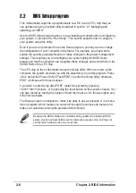
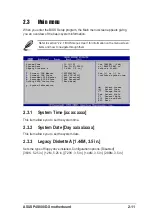
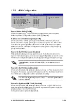
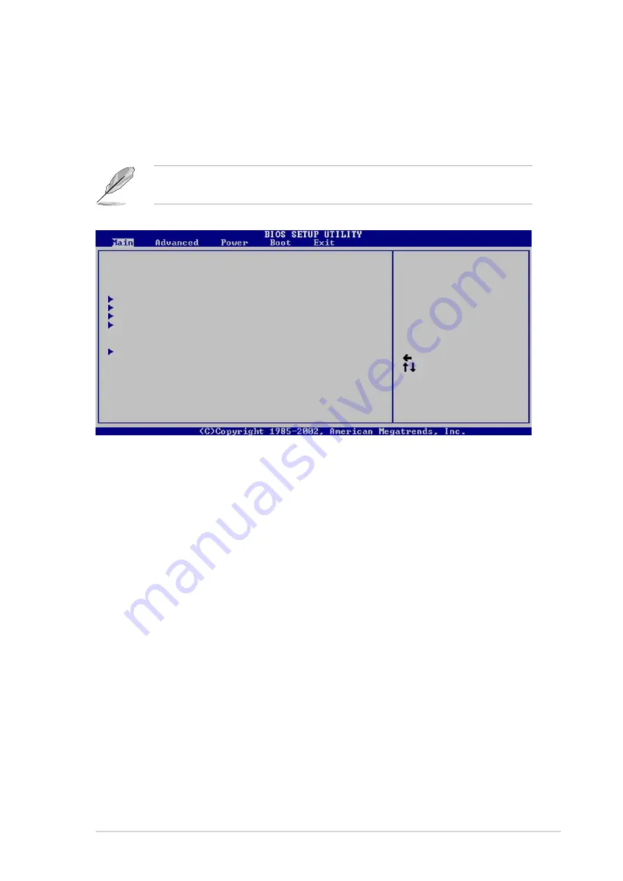
When you enter the BIOS Setup program, the Main menu screen appears giving
you an overview of the basic system information.

2.3.1

System Time [xx:xx:xxxx]

This item allows you to set the system time.

2.3.2

System Date [Day xx/xx/xxxx]

This item allows you to set the system date.

2.3.3

Legacy Diskette A [1.44M, 3.5 in.]

Sets the type of floppy drive installed. Configuration options: [Disabled]
[360K, 5.25 in.] [1.2M , 5.25 in.] [720K , 3.5 in.] [1.44M, 3.5 in.] [2.88M, 3.5 in.]

System Time                 [11:10:19]
System Date                 [Thu 03/27/2003]
Legacy Diskette A           [1.44M, 3.5 in]

   Primary IDE Master      :[ST320413A]
   Primary IDE Slave       :[ASUS CD-S340]
   Secondary IDE Master    :[Not Detected]
   Secondary IDE Slave     :[Not Detected]
OnChip SATA Controller     :[Raid Mode]

   System Information

Use [ENTER], [TAB]
or [SHIFT-TAB] to
select a field.

Use [+] or [-] to
configure system time.

     Select Screen
     Select Item
+-   Change Field
Tab  Select Field
F1   General Help
F10  Save and Exit
ESC  Exit

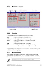
Refer to section “2.2.1  BIOS menu screen” for information on the menu screen
items and how to navigate through them.

Summary of Contents for P4S800D-X

Page 1: ...Motherboard P4S800D X User Guide ...

Page 2: ...A PARTICULAR PURPOSE IN NO EVENT SHALL ASUS ITS DIRECTORS OFFICERS EMPLOYEES OR AGENTS BE LIABLE FOR ANY INDIRECT SPECIAL INCIDENTAL OR CONSEQUENTIAL DAMAGES INCLUDING DAMAGES FOR LOSS OF PROFITS LOSS OF BUSINESS LOSS OF USE OR DATA INTERRUPTION OF BUSINESS AND THE LIKE EVEN IF ASUS HAS BEEN ADVISED OF THE POSSIBILITY OF SUCH DAMAGES ARISING FROM ANY DEFECT OR ERROR IN THIS MANUAL OR PRODUCT SPECI...

Page 3: ... 8 1 7 3 Installing a DIMM 1 9 1 8 Expansion slots 1 10 1 8 1 Standard interrupt assignments 1 10 1 8 2 IRQ assignments for this motherboard 1 10 1 8 3 PCI slots 1 11 1 8 4 AGP slot 1 11 1 9 Jumpers 1 12 1 10 Connectors 1 14 1 10 1 Rear panel connectors 1 14 1 10 2 Internal connectors 1 15 Chapter 2 BIOS information 2 1 Managing and updating your BIOS 2 2 2 1 1 Creating a bootable floppy disk 2 2 ...

Page 4: ... 2 4 5 PCI PnP 2 19 2 4 6 USB Configuration 2 20 2 4 7 Instant Music Configuration 2 21 2 5 Power menu 2 22 2 5 1 Suspend Mode 2 22 2 5 2 Repost Video on S3 Resume 2 22 2 5 3 ACPI 2 0 Support 2 22 2 5 4 ACPI APIC Support 2 22 2 5 5 APM Configuration 2 23 2 5 6 Hardware Monitor 2 24 2 6 Boot menu 2 25 2 6 1 Boot Device Priority 2 25 2 6 3 Removable Drives 2 26 2 6 4 Boot Settings Configuration 2 26...

Page 5: ...he party responsible for compliance could void the user s authority to operate this equipment Safety information Electrical safety To prevent electrical shock hazard disconnect the power cable from the electrical outlet before relocating the system When adding or removing devices to or from the system ensure that the power cables for the devices are unplugged before the signal cables are connected...

Page 6: ...and adding devices on it carefully read all the manuals that came with the package Before using the product make sure all cables are correctly connected and the power cables are not damaged If you detect any damage contact your dealer immediately To avoid short circuits keep paper clips screws and staples away from connectors slots sockets and circuitry Avoid dust humidity and temperature extremes...

Page 7: ... x AGP 8X 4X 1 5V only 5 x PCI 2 x UltraDMA 133 100 2 x Serial ATA with RAID 0 1 function ADI AD1888 SoundMAX 6 channel audio CODEC S PDIF out interface Integrated 10 100 Ethernet controller with Realtek LAN PHY ASUS EZ Flash ASUS CrashFree BIOS2 ASUS Instant Music Lite ASUS MyLogo2 ASUS JumperFree ASUS C P R CPU Parameter Recall CPU Memory and AGP voltage adjustable SFS Stepless Frequency Selecti...

Page 8: ...tional 4 USB 2 0 ports 2 x Serial ATA ports 4Mb Flash ROM ASUS JumperFree AMI BIOS PnP DMI2 0 WfM2 0 SM BIOS 2 3 ASUS EZ Flash ASUS MyLogo2 ASUS CrashFree BIOS2 ASUS C P R ASUS Instant Music Lite PCI 2 2 USB 2 0 1 1 WfM2 0 DMI2 0 WOR WOL Chassis intrusion ATX form factor 12 in x 9 6 in 30 5 cm x 24 5 cm Device drivers ASUS PC Probe ASUS LiveUpdate Trend Micro PC cillin 2004 anti virus software Int...

Page 9: ... This chapter describes the features of the P4S800D X motherboard It includes brief descriptions of the motherboard components and illustrations of the layout jumper settings and connectors Product introduction ...

Page 10: ...latest Intel Pentium 4 Processor via a 478 pin surface mount ZIF socket The Pentium 4 processor with 512KB L2 cache on 0 13 micron processor includes a 800 533 400 MHz system bus Intel Hyper Threading Technology and the FMB2 power design that allows up to 3 2 GHz core frequencies for up to 6 4GB s data transfer rates See page 1 6 Dual Channel DDR memory support Employing the Double Data Rate DDR m...

Page 11: ...n the BIOS codes and data are corrupted This protection eliminates the need to buy a replacement ROM chip AGP 8X support AGP 8X AGP 3 0 is the next generation VGA interface specification that enables enhanced graphics performance with high bandwidth speeds up to 2 12 GB s With a bus of 533Mhz AGP 8X is twice as fast as AGP 4X 8 USB 2 0 ports The motherboard implements the new Universal Serial Bus ...

Page 12: ...ven before entering the operating system Just press the ASUS Instant Music special function keys and enjoy the music See page 2 21 1 4 Before you proceed Take note of the following precautions before you install motherboard components or change any motherboard settings Before you install or remove any component ensure that the ATX power supply is switched off or the power cord is detached from the...

Page 13: ...ort AGP1 CPU_FAN1 FP_AUDIO AD1888 USB2 0 T USB3 B USB4 Top RJ 45 GAME1 Socket 478 ATX12V1 CHASSIS1 DDR DIMM_B1 64 bit 184 pin module PCI2 PCI3 PCI4 PCI5 CLRTC1 PRI_IDE1 SEC_IDE1 PARALLEL PORT COM1 SPDIF_O ATXPWR1 DDR DIMM_A1 64 bit 184 pin module DDR DIMM_A2 64 bit 184 pin module DDR DIMM_B2 64 bit 184 pin module CHA_FAN1 SiS 964 SiS 655 FX SATA2 USB56 SB_PWR1 SATA1 USBPW12 USBPW34 USBPW56 USBPW78...

Page 14: ...damage the CPU P4S800D X P4S800D X CPU Socket 478 Gold Arrow Do not overtighten the screws Doing so may damage the motherboard 1 5 2 Placement direction When installing the motherboard make sure that you place it into the chassis in the correct orientation The edge with external ports goes to the rear part of the chassis as indicated in the image below 1 5 3 Screw holes Place nine 9 screws into th...

Page 15: ...e socket such that its marked corner matches the base of the socket lever 4 Carefully insert the CPU into the socket until it fits in place The CPU fits only in one correct orientation DO NOT force the CPU into the socket to prevent bending the pins and damaging the CPU 5 When the CPU is in place push down the socket lever to secure the CPU The lever clicks on the side tab to indicate that it is l...

Page 16: ...install 64MB 128MB 256MB 512MB and 1GB DDR DIMMs into the DIMM sockets using the memory configurations in this section Important notes 1 Installing DDR DIMMs other than the recommended configurations may cause memory sizing error or system boot failure Use any of the recommended configurations in Table 1 2 In dual channel configurations always install an identical the same type and size DDR DIMM p...

Page 17: ... A DDR DIMM is keyed with a notch so that it fits in only one direction DO NOT force a DIMM into a socket to avoid damaging the DIMM Unlocked Retaining Clip DDR DIMM notch Size Vendor Part No Brand Side s Chip Number 256MB KINGSTON KVR400X64C3A 256 Hynix SS HY5DU56822BT D43 512MB KINGSTON KVR400X64C3A 512 Hynix DS HY5DU56822BT D43 256MB KINGSTON KVR400X64C3A 256 Infineon SS HYB25D256800BT 5B 512MB...

Page 18: ...rivers support Share IRQ or that the cards do not need IRQ assignments Otherwise conflicts will arise between the two PCI groups making the system unstable and the card inoperable 1 8 2 IRQ assignments for this motherboard A B C D E F G H PCI slot 1 shared PCI slot 2 shared PCI slot 3 shared PCI slot 4 shared PCI slot 5 shared AGP slot shared Onboard USB 1 1 2 0 controller used used used used Onbo...

Page 19: ...ions 1 8 4 AGP slot The Accelerated Graphics Port AGP slot that supports AGP 8X 4X 1 5V cards When you buy an AGP card make sure that you ask for one with 1 5V specification Note the notches on the card golden fingers to ensure that they fit the AGP slot on the motherboard Install only 1 5V AGP cards P4S800D X P4S800D X Accelerated Graphics Port AGP Keyed for 1 5v ...

Page 20: ... 2 3 Keep the cap on pins 2 3 for about 5 10 seconds then move the cap back to pins 1 2 3 Plug the power cord and turn ON the computer 4 Hold down the Del key during the boot process and enter BIOS setup to re enter data Except when clearing the RTC RAM never remove the cap on CLRTC1 jumper default position Removing the cap will cause system boot failure You do not need to clear the RTC when the s...

Page 21: ...port this feature The USBPW12 and USBPW34 jumpers are for the rear USB ports The USBPW56 and USBPW78 jumpers are for the internal USB header that you can connect to the front USB ports 1 This feature requires a power supply that can provide at least 1A on the 5VSB lead when these jumpers are set to 5VSB Otherwise the system would not power up 2 The total current consumed must NOT exceed the power ...

Page 22: ...ack This Mic pink jack connects a microphone In 6 channel mode the function of this jack becomes Rear Speaker Out 7 USB 2 0 ports 1 and 2 These two 4 pin Universal Serial Bus USB ports are available for connecting USB 2 0 devices 8 USB 2 0 ports 3 and 4 These two 4 pin Universal Serial Bus USB ports are available for connecting USB 2 0 devices 9 Serial connector This 9 pin COM1 port is for serial ...

Page 23: ...o match the covered hole on the UltraATA cable connector This prevents incorrect orientation when you connect the cables 3 The hole near the blue connector on the UltraATA cable is intentional 2 Floppy disk drive connector 34 1 pin FLOPPY1 This connector supports the provided floppy drive ribbon cable After connecting one end to the motherboard connect the other end to the floppy drive Pin 5 is re...

Page 24: ...de 8A on the 12V lead and at least 1A on the 5 volt standby lead 5VSB The minimum recommended wattage is 230W or 300W for a fully configured system The system may become unstable and may experience difficulty powering up if the power supply is inadequate 4 Internal audio connectors 4 pin CD1 AUX1 These connectors allow you to receive stereo audio input from sound sources such as a CD ROM TV tuner ...

Page 25: ...B header 10 1 pin USB56 USB78 If the USB ports on the rear panel are inadequate a USB header is available for additional USB ports Connect the USB cable of the USB 2 0 module to this header You may install the USB module in the chassis front panel The module has two USB 2 0 ports for connecting next generation USB peripherals such as high resolution cameras scanners and printers NEVER connect a 13...

Page 26: ...ut_R Line out_L BLINE_OUT_R NC MICPWR 5VA AGND 8 Chassis intrusion connector 4 1 pin CHASSIS1 This lead is for a chassis designed with intrusion detection feature This requires an external detection mechanism such as a chassis intrusion sensor or microswitch When you remove any chassis component the sensor triggers and sends a high level signal to this lead to record a chassis intrusion event By d...

Page 27: ...tor supports a GAME MIDI module If a GAME MIDI module is available connect the GAME MIDI cable to this connector The GAME MIDI port on the module connects a joystick or a game pad for playing games and MIDI devices for playing or editing audio files The GAME MIDI module is purchased separately P4S800D X P4S800D X Game connector GAME1 5V 5V J2B1 J2CX MIDI_OUT J2CY J2B2 MIDI_IN J1B1 J1CX GND GND J1C...

Page 28: ... the power switch turns the system between ON and SLEEP or ON and SOFT OFF depending on the BIOS or OS settings Pressing the power switch while in the ON mode for more than 4 seconds turns the system OFF Reset Switch Lead Blue 2 pin RESET This 2 pin connector connects to the case mounted reset switch for rebooting the system without turning off the system power Hard disk activity LED Red 2 pin IDE...

Page 29: ...Chapter 2 This chapter tells how to change system settings through the BIOS Setup menus Detailed descriptions of the BIOS parameters are also provided BIOS information ...

Page 30: ...loppy disk drive b Click Start from the Windows desktop then select My Computer c Select the 3 1 2 Floppy Drive icon d Click File from the menu then select Format A Format 3 1 2 Floppy Disk window appears e Select Create an MS DOS startup disk from the format options field then click Start Windows 2000 environment To create a set of boot disks for Windows 2000 a Insert a formatted high density 1 4...

Page 31: ...ty Version 1 10 Copyright C 2002 American Megatrends Inc All rights reserved Reading flash done A 2 1 2 Using AFUDOS to copy the current BIOS The AFUDOS EXE utility can also be used to copy the current system BIOS settings to a floppy or hard disk The copy can be used as a backup in case the system BIOS fails or gets corrupted 1 At the DOS prompt type the command line afudos o filename where filen...

Page 32: ...s is complete the utility returns to the DOS prompt A afudos iP4S800DX ROM AMI Firmware Update Utility Version 1 10 Copyright C 2002 American Megatrends Inc All rights reserved Reading file done Erasing flash done Writing flash 0x0008CC00 9 Verifying flash done A DO NOT shutdown or reset the system while updating the BIOS Doing so may cause system boot failure The BIOS information on the screen is...

Page 33: ...tem 3 To launch EZ Flash press Alt F2 during POST to display the following 4 Insert the floppy disk that contains the BIOS file If the P4S800DX ROM file is found in the floppy disk EZ Flash performs the BIOS update process and automatically reboots the system when done DO NOT shutdown or reset the system while updating the BIOS Doing so may cause system boot failure User recovery requested Startin...

Page 34: ...n 2 1 1 Creating a bootable floppy disk To recover the BIOS from a floppy disk 1 Boot the system 2 When a corrupted BIOS is detected the following message appears Bad BIOS checksum Starting BIOS recovery Checking for floppy 3 Insert a floppy disk that contains the original or the latest BIOS file for this motherboard P4S800DX ROM If the BIOS file that you downloaded from the ASUS website has a dif...

Page 35: ...ed BIOS is detected the following screen message appears Bad BIOS checksum Starting BIOS recovery Checking for floppy 3 Place the support CD in the CD ROM The support CD contains the original BIOS for this motherboard DO NOT shutdown or reset the system while updating the BIOS Doing so may cause system boot failure 4 When the BIOS update process is complete reboot the system Bad BIOS checksum Star...

Page 36: ...and record them in the CMOS RAM of the LPC chip The LPC chip on the motherboard stores the Setup utility When you start up the computer the system provides you with the opportunity to run this program Press Del during the Power On Self Test POST to enter the Setup utility otherwise POST continues with its test routines If you wish to enter Setup after POST restart the system by pressing Ctrl Alt D...

Page 37: ...eys At the bottom right corner of a menu screen are the navigation keys for that particular menu Use the navigation keys to select items in the menu and change the settings System Time 11 10 19 System Date Thu 03 27 2003 Legacy Diskette A 1 44M 3 5 in Primary IDE Master ST320413A Primary IDE Slave ASUS CD S340 Secondary IDE Master Not Detected Secondary IDE Slave Not Detected OnChip SATA Controlle...

Page 38: ...Pop up window Select a menu item then press Enter to display a pop up window with the configuration options for that item 2 2 8 Scroll bar A scroll bar appears on the right side of a menu screen when there are items that do not fit on the screen Press Up Down arrow keys or PageUp PageDown keys to display the other items on the screen 2 2 9 General help At the top right corner of the menu screen is...

Page 39: ...isabled 360K 5 25 in 1 2M 5 25 in 720K 3 5 in 1 44M 3 5 in 2 88M 3 5 in System Time 11 10 19 System Date Thu 03 27 2003 Legacy Diskette A 1 44M 3 5 in Primary IDE Master ST320413A Primary IDE Slave ASUS CD S340 Secondary IDE Master Not Detected Secondary IDE Slave Not Detected OnChip SATA Controller Raid Mode System Information Use ENTER TAB or SHIFT TAB to select a field Use or to configure syste...

Page 40: ... LBA mode Setting to Auto enables the LBA mode if the device supports this mode and if the device was not previously formatted with LBA mode disabled Configuration options Disabled Auto Block Multi sector Transfer Auto Enables or disables data multi sectors transfers When set to Auto the data transfer from and to the device occurs multiple sectors at a time if the device supports multi sector tran...

Page 41: ...u to enable or disable the onchip Serial ATA controller Configuration options Disabled Enabled Select Screen Select Item Change Option F1 General Help F10 Save and Exit ESC Exit AMI BIOS Version 08 00 08 Build Date 03 12 03 ID P4C81029 Processor Type Intel R Pentium R 4 CPU 1 73GHz Speed 1733 MHz Count 1 System Memory Size 256MB 2 3 6 System Information This menu gives you an overview of the gener...

Page 42: ...ilable options 2 4 Advanced menu The Advanced menu items allow you to change the settings for the CPU and other system devices JumperFree Configuration CPU Configuration Chipset Onboard Devices Configuration PCI PnP USB Configuration Speech Configuration Instant Music Configuration Configure CPU Select Screen Select Item Enter Go to Sub screen F1 General Help F10 Save and Exit ESC Exit 2 4 1 Jumpe...

Page 43: ...ed This item allows you to enable or disable the maximum CPUID value limit Configuration options Disabled Enabled CPU Internal Thermal Control Auto This item allows you to disable or set to auto the CPU internal thermal control feature Configuration options Auto Disabled Hyper Threading Technology Enabled Allows you to enable or disable the processor Hyper Threading Technology This item appears on...

Page 44: ...M CAS Latency By SPD DRAM Precharge Display Auto DRAM RAS to CAS Delay Auto DRAM RAS Precharge Auto Graphic Adapter Priority PCI Allows selection of the graphics controller to use as primary boot device Configuration options PCI AGP Graphics Aperture Size 64MB Allows you to select the size of mapped memory for AGP graphic data Configuration options 32MB 64MB 128MB 256MB Advanced HyperStreaming Eng...

Page 45: ...ency between the SDRAM read command and the time the data actually becomes available Configuration options By SPD 2T 2 5T 3T DRAM Precharge Delay Auto Configuration options Auto 6T 7T 5T 4T 8T 9T DRAM RAS to CAS Delay Auto This item controls the latency between the DDR SDRAM active command and the read write command Configuration options Auto 3T 2T 4T 5T DRAM RAS Precharge Auto This item controls ...

Page 46: ...AN item is set to Enabled Configuration options Disabled Enabled 2 4 4 Onboard Devices Configuration Serial Port1 Address 3F8 IRQ4 Parallel Port Address Disabled Parallel Port Mode Normal Parallel Port IRQ IRQ7 OnBoard Game MIDI Port Disabled Configure Win637 Super IO Chipset Serial Port1 Address 3F8 IRQ4 Allows you to select the Serial Port1 base address Configuration options Disabled 3F8 IRQ4 3E...

Page 47: ...e block for legacy ISA devices Select Screen Select Item Change Option F1 General Help F10 Save and Exit ESC Exit Plug and Play OS No PCI Latency Timer 64 Allocate IRQ to PCI VGA Yes Palette Snooping Disabled PCI IDE BusMaster Enabled Advanced PCI PnP settings WARNING Setting wrong values in the sections below may cause system to malfunction NO Lets the bIOS configure all the devices in the system...

Page 48: ...an IRQ to PCI VGA card if the card requests for an IRQ When set to No BIOS does not assign an IRQ to the PCI VGA card even if requested Configuration options No Yes Pallete Snooping Disabled When set to Enabled the pallete snooping feature informs the PCI devices that an ISA graphics device is installed in the system so that the latter can function correctly Setting to Disabled deactivates this fe...

Page 49: ...0 Mbps or Full Speed 12 Mbps Configuration options HiSpeed Full Speed Stop EHCI HC in OHCI handover Enabled Allows you to enable or disable the feature to stop the EHCI host controller during the OHCI OS handover call This is needed when installing operating systems that do not support EHCI host controllers Configuration options Disabled Enabled Instant Music Disabled Instant Music Option Disable ...

Page 50: ...F10 Save and Exit ESC Exit 2 5 1 Suspend Mode Auto Allows you to select the ACPI state to be used for system suspend Configuration options S1 POS Only S3 Only Auto 2 5 2 Repost Video on S3 Resume No Determines whether to invoke VGA BIOS POST on S3 STR resume Configuration options No Yes 2 5 3 ACPI 2 0 Support No Allows you to add more tables for ACPI 2 0 specifications Configuration options No Yes...

Page 51: ...tion options Always Off Always On Keep Previous State Power On By PS 2 Keyboard Disabled This parameter allows you to use specific keys on the keyboard to turn on the system This feature requires an ATX power supply that provides at least 1A on the 5VSB lead Configuration options Disabled Space Bar Ctrl Esc Power key Power On By Internal MAC LAN Disabled When set to Enabled this parameter allows y...

Page 52: ...TC Alarm Second appear with set values Configuration options Disabled Enabled The computer cannot receive or transmit data until the computer and applications are fully running Thus connection cannot be made on the first try Turning an external modem off and then back on while the computer is off causes an initialization string that turns the system power on Select Screen Select Item Change Option...

Page 53: ...utomatically detects the voltage output through the onboard voltage regulators 2 6 Boot menu The Boot menu items allow you to change the system boot options Select an item then press Enter to display the sub menu Boot Device Priority Hard Disk Drives Boot Settings Configuration Security Specifies the Boot Device Priority sequence Boot Settings 2 6 1 Boot Device Priority 1st Boot Device First Flopp...

Page 54: ... disk drive items that appear on the screen depends on the the number of hard disk drives installed in the system Configuration options xxxxx Drive Disabled 2 6 3 Removable Drives 1st Boot Device 1st FLOPPY DRIVE 2nd Boot Device ASUS USB Flash Disk 3rd Boot Device ASUS USB Flash Disk Removable Drives Specifies the boot sequence from the available devices A device enclosed in 1st xxth Boot Device 1...

Page 55: ...em waits for F1 key to be pressed when error occurs Configuration options Disabled Enabled Hit DEL Message Display Enabled When set to Enabled the system displays the message Press DEL to run Setup during POST Configuration options Disabled Enabled Interrupt 19 Capture Disabled When set to Enabled this function allows the option ROMs to trap Interrupt 19 Configuration options Disabled Enabled Make...

Page 56: ...s then press Enter The password supports only a maximum of 6 characters 3 Confirm the password when prompted The message Password Installed appears after you have successfully set your password The Supervisor Password item now shows Installed To change the supervisor password follow the same steps as in setting a user password To clear the supervisor password select the Change Supervisor Password ...

Page 57: ... Enter Your password should have at least six characters 3 Confirm the password when prompted The message Password Installed appears after you have successfully set your password The User Password item now shows Installed To change the user password follow the same steps as in setting a user password Clear User Password Select this item if you wish to clear the user password Password Check Setup W...

Page 58: ...low you to load the optimal or failsafe default values for the BIOS items and save or discard your changes to the BIOS items Exit Save Changes Exit Discard Changes Discard Changes Load Setup Defaults Exit system setup after saving the changes F10 key can be used for this operation Exit Options Select Screen Select Item Enter Go to Sub screen F1 General Help F10 Save and Exit ESC Exit Exit Save Cha...

Page 59: ...Chapter 3 This chapter describes the contents of the support CD that comes with the motherboard package Software support ...

Page 60: ...E 3 2 Support CD information The support CD that came with the motherboard contains useful software and several utility drivers that enhance the motherboard features 3 2 1 Running the support CD To begin using the support CD simply insert the CD into your CD ROM drive The CD automatically displays the Drivers menu if Autorun is enabled in your computer Click on an item to install The contents of t...

Page 61: ...AID Driver Disk Allows you to create a SIS RAID driver disk SiS Mini IDE driver Installs the SiS mini IDE driver SiS AGP driver Installs the SiS AGP driver SoundMAX Audio Driver and Application Installs the ADI SoundMAX 1888 AC 97 compliant audio controller and application SiS PCI LAN driver Installs the SiS PCI LAN driver USB 2 0 Driver Installs the USB 2 0 drivers 3 2 3 Utilities menu The Utilit...

Page 62: ...computer at a healthy operating condition Install ASUS Update This program allows you to download the latest version of the BIOS from the ASUS website Before using the ASUS Update make sure that you have an Internet connection so you can connect to the ASUS website Installing ASUS Update also installs ASUS Mylogo2 Anti virus Utility This item installs the Tren Micro PC cillin 2004 anti virus progr...

Page 63: ...menu select the item Instant Music and set it to Enabled See section 2 4 Advanced Menu in the user guide 4 Highlight the Instant Music CDROM item and press Enter to display the CD ROM options Select the CD ROM drive that you wish to use for this feature See section 2 4 Advanced Menu in the user guide Make sure to connect the CD ROM audio cable Otherwise you cannot control the audio volume using th...

Page 64: ...o output You may also connect a headphone to the headphone jack on the CD ROM drive front panel 4 Press Esc to turn ON Instant Music Lite 5 Place an audio CD on the drive 6 Press F1 or the Space Bar to play the first track on the CD If there is no CD on the drive and you press F1 or Space Bar the drive tray ejects 7 Refer to the Instant Music function key definitions on the previous page to select...

Reviews: