

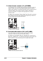
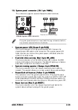


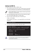

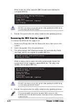


ASUS P5P800
ASUS P5P800
ASUS P5P800
ASUS P5P800
ASUS P5P800
Chapter summary
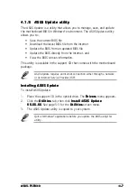
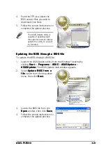
4.1
Managing and updating your BIOS ........................................ 4-1
4.2
BIOS setup program ........................................................... 4-10
4.3
Main menu .......................................................................... 4-13
4.4
Advanced menu .................................................................. 4-18
4.5
Power menu ........................................................................ 4-30
4.6
Boot menu .......................................................................... 4-35
4.7
Exit menu ........................................................................... 4-40
Summary of Contents for P5P800
Page 1: ...Motherboard P5P800 ...


