ASUS P7F-C Series
4-23
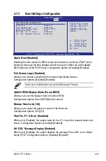
Onboard LAN1/2/3/4 Boot ROM [PXE]
Allows you to configure the onboard LAN1/2/3/4 boot mode.
Configuration: [Disabled] [PXE]
Onboard LAN3/4 Boot ROM
are available only for
P7F-C/4L
model.
LSI 1068E Boot ROM [Enabled]
Allows you to configure the onboard LSI 1068E boot mode.
Configuration: [Enabled] [Disabled]
LSI 1068E Boot ROM
is available only for
P7F-C/SAS
model.
Serial Port1 Address [3F8/IRQ4]
Allows you to select the Serial Port1 base address.
Configuration options: [Disabled] [3F8/IRQ4] [3E8/IRQ4] [2E8/IRQ3]
Serial Port2 Address [2F8/IRQ3]
Allows you to select the Serial Port2 base address.
Configuration options: [Disabled] [2F8/IRQ3] [3E8/IRQ4] [2E8/IRQ3]
Parallel Port Address [378]
Allows you to select the Parallel Port base address.
Configuration options: [Disabled] [378] [278] [3BC]
Parallel Port Mode [Normal]
Allows you to select the Parallel Port mode.
Configuration options: [Normal] [Bi-Directional] [ECP] [EPP] [ECP & EPP]
Interrupt 19 Capture [Enabled]
When set to [Enabled], this function allows the option ROMs to trap Interrupt 19.
Configuration options: [Disabled] [Enabled]
Summary of Contents for P7F-C
Page 1: ...Motherboard P7F C Series P7F C SAS P7F C 4L ...
Page 23: ...ASUS P7F C Series 2 5 2 2 3 Motherboard layout P7F C SAS ...
Page 24: ...2 6 Chapter 2 Hardware information P7F C 4L ...
Page 52: ...2 34 Chapter 2 Hardware information ...
Page 96: ...4 40 Chapter 4 BIOS setup ...
Page 150: ...5 54 Chapter 5 RAID configuration ...
Page 179: ...ASUS P7F C Series A 3 A 1 P7F C SAS Series block diagram ...
Page 180: ...A 4 Appendix A Reference information A 2 P7F C 4L Series block diagram ...


