background image

Motherboard

PRIME Z270-P 

Summary of Contents for PRIME Z270-P

Page 1: ...Motherboard PRIME Z270 P ...

Page 2: ...espective companies and are used only for identification or explanation and to the owners benefit without intent to infringe Offer to Provide Source Code of Certain Software This product contains copyrighted software that is licensed under the General Public License GPL under the Lesser General Public License Version LGPL and or other Free Open Source Software Licenses Such software in this produc...

Page 3: ...PU 1 3 1 4 System memory 1 7 1 5 Expansion slots 1 10 1 6 Headers 1 12 1 7 Connectors 1 13 1 9 Software support 1 22 Chapter 2 BIOS information 2 1 Managing and updating your BIOS 2 1 2 2 BIOS setup program 2 6 2 3 My Favorites 2 16 2 4 Main menu 2 18 2 5 Ai Tweaker menu 2 20 2 6 Advanced menu 2 29 2 7 Monitor menu 2 38 2 8 Boot menu 2 41 2 9 Tool menu 2 45 2 10 Exit menu 2 47 Appendices Notices A...

Page 4: ...erboard and adding components carefully read all the manuals that came with the package Before using the product ensure all cables are correctly connected and the power cables are not damaged If you detect any damage contact your dealer immediately To avoid short circuits keep paper clips screws and staples away from connectors slots sockets and circuitry Avoid dust humidity and temperature extrem...

Page 5: ...ks properly take note of the following symbols used throughout this manual DANGER WARNING Information to prevent injury to yourself when completing a task CAUTION Information to prevent damage to the components when completing a task IMPORTANT Instructions that you MUST follow to complete a task NOTE Tips and additional information to help you complete a task Typography Bold text Indicates a menu ...

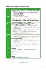
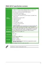
Page 6: ...00 O C 3466 O C 3400 O C 3333 O C 3300 O C 3200 O C 3000 O C 2800 O C 2666 O C 2400 O C 2133 MHz Non ECC Un buffered Memory Dual channel memory architecture Supports Intel Extreme Memory Profile XMP The maximum memory frequency supported varies by processor Refer to www asus com for the latest Memory QVL Qualified Vendors List Expansion slots 1 x PCI Express 3 0 2 0 x16 slot at x16 mode 1 x PCI Ex...

Page 7: ...trace path Audio Shielding Ensures precision analog digital separation and greatly reduces multi lateral interference Dedicated audio PCB layers Separate layers for left and right channels to guard the quality of the sensitive audio signals Premium Japanese audio capacitors Provide warm natural and immersive sound with exceptional clarity and fidelity Supports jack detection and front panel jack r...

Page 8: ...ble CPU Core voltage at 0 005V increment iGPU Adjustable CPU Graphics voltage at 0 005V increment vCCIO Adjustable Analog and Digital I O voltage at 0 005V increment vCCSA Adjustable CPU System Agent voltage at 0 1V increment vDRAM Bus 160 step Memory voltage control vPCH 3 step Chipset voltage control SFS Stepless Frequency Selection BCLK PCIE frequency tuning from 98MHz up to 538MHz at 0 1MHz in...

Page 9: ...Chassis Q Fan control setting is set to Auto mode which detects the CPU and chassis fans installed and changes the control mode automatically BIOS features 128 Mb Flash ROM UEFI AMI BIOS PnP DMI3 0 WfM2 0 SM BIOS 3 0 ACPI 6 0 Multi language BIOS ASUS EZ Flash 3 CrashFree BIOS 3 F11 EZ Tuning Wizard F6 Qfan Control F3 My Favorites Last Modified log F12 PrintScreen and ASUS DRAM SPD Serial Presence ...

Page 10: ...x ...

Page 11: ...onent ensure that the ATX power supply is switched off or the power cord is detached from the power supply Failure to do so may cause severe damage to the motherboard peripherals or components 1 2 Motherboard overview Before you install the motherboard study the configuration of your chassis to ensure that the motherboard fits Unplug the power cord before installing or removing the motherboard Fai...

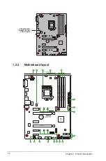
Page 12: ...RY Super I O 2280 2260 2242 2280 2260 2242 KBMS DVI 22 1cm 8 7in DDR4 DIMM_A1 64bit 288 pin module DDR4 DIMM_A2 64bit 288 pin module DDR4 DIMM_B1 64bit 288 pin module DDR4 DIMM_B2 64bit 288 pin module LAN_USB910 USB3_78 USB3_56 HDMI CHA_FAN2 CPU_FAN CHA_FAN1 30 5cm 12in LGA1151 DIGI VRM COM EATX12V USB3_12 USB3_34 Intel Z270 128Mb BIOS PANEL AUDIO SATA6G_2 SATA6G_1 SATA6G_4 SATA6G_3 LANGuard PCIE ...

Page 13: ...tors 4 pin CPU_FAN 4 pin CHA_FAN1 2 1 20 3 Intel LGA1151 CPU socket 1 3 4 DDR4 DIMM slots 1 7 5 USB 3 0 connector 20 1 pin USB3_12 USB3_34 1 16 6 M 2 Socket 3 1 18 7 Intel Z270 Serial ATA 6 0 Gb s connector 7 pin SATA6G_1 4 1 19 8 Clear RTC RAM 2 pin CLRTC 1 12 9 System panel connector 20 5 pin PANEL 1 21 10 USB 2 0 connectors 10 1 pin USB1112 USB1314 1 15 11 Serial port connectors 10 1 pin COM 1 ...

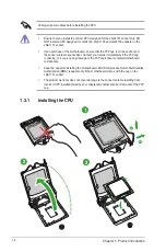
Page 14: ... cap is on the socket and the socket contacts are not bent Contact your retailer immediately if the PnP cap is missing or if you see any damage to the PnP cap socket contacts motherboard components Keep the cap after installing the motherboard ASUS will process Return Merchandise Authorization RMA requests only if the motherboard comes with the cap on the LGA1151 socket The product warranty does n...

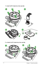
Page 15: ...ASUS PRIME Z270 P 1 5 A B C 5 4 1 3 2 CPU heatsink and fan assembly installation Apply the Thermal Interface Material to the CPU heatsink and CPU before you install the heatsink and fan if necessary ...

Page 16: ...1 6 Chapter 1 Product introduction 3 4 A B B A To uninstall the CPU heatsink and fan assembly 2 1 To install the CPU heatsink and fan assembly 2 B A A B 1 ...

Page 17: ...R DDR2 or DDR3 memory module to the DDR4 slot According to Intel CPU spec DIMM voltage below 1 35 V is recommended to protect the CPU 1 4 2 Memory configurations You may install 2 GB 4 GB 8 GB 16 GB 32GB and 64GB unbuffered non ECC DDR4 DIMMs into the DIMM sockets You can refer to the recommended memory population below Recommended memory configurations DIMM_A1 DIMM_A2 DIMM_B1 DIMM_B2 PRIME Z270 P...

Page 18: ...support a full memory load 4 DIMMs or overclocking condition You may install varying memory sizes in Channel A and Channel B The system maps the total size of the lower sized channel for the dual channel configuration Any excess memory from the higher sized channel is then mapped for single channel operation According to Intel CPU spec DIMM voltage below 1 35V is recommended to protect the CPU Due...

Page 19: ...ASUS PRIME Z270 P 1 9 1 4 3 Installing a DIMM 1 2 3 To remove a DIMM B A ...

Page 20: ...ed on the slot 5 Secure the card to the chassis with the screw you removed earlier 6 Replace the system cover 1 5 2 Configuring an expansion card After installing the expansion card configure it by adjusting the software settings 1 Turn on the system and change the necessary BIOS settings if any See Chapter 2 for information on BIOS setup 2 Assign an IRQ to the card 3 Install the software drivers ...

Page 21: ...g multiple graphics cards for better thermal environment VGA configuration PCI Express operating mode PCIe 3 0 x16_1 gray PCIe 3 0 x16_2 black x4 mode Single VGA PCIe card x16 Recommended for single VGA card N A Dual VGA PCIe cards x16 x4 IRQ assignments for this motherboard A B C D E F G H HD Audio Controller shared XHCI shared SATA Controller shared LAN Controller shared PCIEx1_1 shared PCIEx1_2...

Page 22: ...p information such as system passwords To erase the RTC RAM 1 Turn OFF the computer and unplug the power cord 2 Use a metal object such as a screwdriver to short the two pins 3 Plug the power cord and turn on the computer 4 Hold down the Del key during the boot process and enter BIOS setup to re enter data If the steps above do not help remove the onboard battery and short the two pins again to cl...

Page 23: ...se 2 LAN RJ 45 port This port allows Gigabit connection to a Local Area Network LAN through a network hub LAN port LED indications LAN port Speed LED Activity Link LED Activity Link LED Speed LED Status Description Status Description Off No link OFF 10Mbps connection Orange Linked ORANGE 100Mbps connection Orange Blinking Data activity GREEN 1Gbps connection Orange Blinking then steady Ready to wa...

Page 24: ...ices can only be used under Windows OS environment and after the USB 3 0 driver installation We strongly recommend that you connect USB 3 0 devices to USB 3 0 ports for faster and better performance from your USB 3 0 devices 8 HDMI port This port is for a High Definition Multimedia Interface HDMI connector and is HDCP compliant allowing playback of HD DVD Blu ray and other protected content 9 DVI ...

Page 25: ...o any of these connectors then install the module to a slot opening at the back of the system chassis These USB connectors comply with USB 2 0 specifications and supports up to 480Mbps connection speed PIN 1 COM DCD TXD GND RTS RI RXD DTR DSR CTS PRIME Z270 P Serial port COM connector PRIME Z270 P Never connect a 1394 cable to the USB connectors Doing so will damage the motherboard The USB 2 0 mod...

Page 26: ...D IntA_P1_D IntA_P1_D GND PIN 1 USB3 5V IntA_P2_SSRX IntA_P2_SSRX GND IntA_P2_SSTX IntA_P2_SSTX GND IntA_P2_D IntA_P2_D USB3_34 USB3 5V IntA_P1_SSRX IntA_P1_SSRX GND IntA_P1_SSTX IntA_P1_SSTX GND IntA_P1_D IntA_P1_D GND PIN 1 USB3 5V IntA_P2_SSRX IntA_P2_SSRX GND IntA_P2_SSTX IntA_P2_SSTX GND IntA_P2_D IntA_P2_D PRIME Z270 P USB3 0 Front panel connectors PRIME Z270 P A B A B SPDIF_OUT 5V SPDIFOUT ...

Page 27: ...about the minimum power supply requirement for your system refer to the Recommended Power Supply Wattage Calculator at http support asus com PowerSupplyCalculator PSCalculator aspx SLanguage en us for details 5 ATX power connectors 24 pin EATXPWR 8 pin ATX12V These connectors are for ATX power supply plugs The power supply plugs are designed to fit these connectors in only one orientation Find the...

Page 28: ...efinition front panel audio module to this connector set the Front Panel Type item in the BIOS setup to HD If you want to connect an AC 97 front panel audio module to this connector set the item to AC97 By default this connector is set to HD AAFP AGND NC SENSE1_RETUR SENSE2_RETUR PORT1 L PORT1 R PORT2 R SENSE_SEND PORT2 L HD audio compliant pin definition PIN 1 AGND NC NC NC MIC2 MICPWR Line out_R...

Page 29: ...eparately 8 Intel Z270 Serial ATA 6 0Gb s connectors 7 pin SATA6G_1 4 These connectors connect to Serial ATA 6 0 Gb s hard disk drives via Serial ATA 6 0 Gb s signal cables SATA6G_4 SATA6G_2 GND RSATA_TXP4 RSATA_TXN4 GND RSATA_RXN4 RSATA_RXP4 GND GND RSATA_RXP2 RSATA_RXN2 GND RSATA_TXN2 RSATA_TXP2 GND SATA6G_3 SATA6G_1 GND RSATA_TXP3 RSATA_TXN3 GND RSATA_RXN3 RSATA_RXP3 GND GND RSATA_RXP1 RSATA_RX...

Page 30: ...nector supports a CPU fan of maximum 1A 12 W fan power 9 CPU and chassis fan connectors 4 pin CPU_FAN 4 pin CHA_FAN 1 2 Connect the fan cables to the fan connectors on the motherboard ensuring that the black wire of each cable matches the ground pin of the connector CHA FAN PWM CHA FAN IN CHA FAN PWR GND CPU_FAN CHA_FAN1 CPU FAN PWM CPU FAN IN CPU FAN PWR GND CHA_FAN2 GND CHA FAN PWR CHA FAN IN CH...

Page 31: ...ker allows you to hear system beeps and warnings ATX power button soft off button 2 pin PWR_SW This connector is for the system power button Pressing the power button turns the system on or puts the system in sleep or soft off mode depending on the operating system settings Pressing the power switch for more than four seconds while the system is ON turns the system OFF Reset button 2 pin RESET Thi...

Page 32: ...oftware applications and utilities that you can install to avail all motherboard features The contents of the Support DVD are subject to change at any time without notice Visit the ASUS website at www asus com for updates The following screen is for reference only To run the Support DVD Place the Support DVD into the optical drive If Autorun is enabled in your computer the DVD automatically displa...

Page 33: ...herboard s softwares drivers and the BIOS version easily With this utlity you can also manually update the saved BIOS and select a boot logo when the system goes into POST To launch EZ Update click EZ Update on the AI Suite 3 main menu bar BIOS information 2 EZ Update requires an Internet connection either through a network or an ISP Internet Service Provider Click to automatically update your mot...

Page 34: ...low the steps below to update the BIOS via USB or Internet Via USB a Insert the USB flash disk that contains the latest BIOS file to the USB port then select by USB b Press Tab to switch to the Drive field c Press the Up Down arrow keys to find the USB flash disk that contains the latest BIOS and then press Enter d Press Tab to switch to the Folder Info field e Press the Up Down arrow keys to find...

Page 35: ...system 2 Insert the support DVD to the optical drive or the USB flash drive that contains the BIOS file to the USB port 3 The utility automatically checks the devices for the BIOS file When found the utility reads the BIOS file and enters ASUS EZ Flash 3 utility automatically 4 The system requires you to enter BIOS Setup to recover BIOS settings To ensure system compatibility and stability we reco...

Page 36: ...P2 ST3808110AS 76319MB aigo miniking 250MB UEFI FAT ASUS DRW 2014L1T 4458MB P1 ASUS DRW 2014L1T 4458MB UEFI FAT aigo miniking 250MB Enter Setup 4 When the booting message appears press Enter within five 5 seconds to enter FreeDOS prompt Welcome to FreeDOS http www freedos org C d D 5 On the FreeDOS prompt type d then press Enter to switch the disk from Drive C optical drive to Drive D USB flash dr...

Page 37: ...le and press Enter 4 After the BIOS Updater checks the selected BIOS file select Yes to confirm the BIOS update Are you sure you want to update the BIOS Yes No The BIOS Backup feature is not supported due to security regulations 5 Press any key to reboot the system to automatically launch EZ Flash 3 Wait until the BIOS update is completed DO NOT shut down or reset the system while updating the BIO...

Page 38: ...end you always shut down the system properly from the operating system The BIOS setup screens shown in this section are for reference purposes only and may not exactly match what you see on your screen Visit the ASUS website at www asus com to download the latest BIOS file for this motherboard Ensure that a USB mouse is connected to your motherboard if you want to use the mouse to control the BIOS...

Page 39: ...y depending on the devices you installed to the system Saves the changes and resets the system Selects the display language of the BIOS setup program Displays the CPU motherboard temperature CPU voltage output CPU chassis fan speed and SATA information Displays the system properties of the selected mode Click Enter to switch EZ System Tuning modes Displays the Advanced mode menus Selects the boot ...

Page 40: ... motherboard temperature CPU and memory voltage output 2 2 2 Advanced Mode The Advanced Mode provides advanced options for experienced end users to configure the BIOS settings The figure below shows an example of the Advanced Mode Refer to the following sections for the detailed configurations To access the EZ Mode click EzMode F7 or press F7 Popup window Searches FAQ 2 8 Chapter 2 Getting started...

Page 41: ...6 This button above the menu bar displays the current settings of your fans Use this button to manually tweak the fans to your desired settings Refer to section 2 2 3 QFan Control for more information EZ Tuning Wizard F11 This button above the menu bar allows you to view and tweak the overclocking settings of your system It also allows you to change the motherboard s SATA mode from AHCI to RAID mo...

Page 42: ...r of the menu screen is a brief description of the selected item Use F12 key to capture the BIOS screen and save it to the removable storage device Configuration fields These fields show the values for the menu items If an item is user configurable you can change the value of the field opposite the item You cannot select an item that is not user configurable A configurable field is highlighted whe...

Page 43: ...ofile or manually configure the operating speed of your CPU and chassis fans Click to select a fan to be configured Click to undo the changes Click to apply the fan setting Click to go back to main menu Select a profile to apply to your fans ASUS PRIME Z270 P 2 11 ...

Page 44: ... speed To configure your fans 1 Select the fan that you want to configure and to view its current status 2 Click and drag the speed points to adjust the fans operating speed 3 Click Apply to save the changes then click Exit ESC Speed points Click to manually configure your fans 2 12 Chapter 2 Getting started ...

Page 45: ...eyboard or click from the BIOS screen to open EZ Tuning Wizard screen then click Next 2 Select a PC scenario Daily Computing or Gaming Media Editing then click Next 3 Select the CPU fan type Box cooler Tower cooler or Water cooler that you installed then click Next If you are not sure of the CPU fan type click I m not sure The system automatically detects the CPU fan type 4 Click Next then click Y...

Page 46: ...ard screen 2 Click RAID then click Yes to enable RAID Ensure that your HDDs have no existing RAID volumes Ensure to connect your HDDs to Intel SATA connectors or PCIE ports 3 Select PCIE or SATA then click Next to continue 4 The available HDDs are displayed Click Next to continue 2 14 Chapter 2 Getting started ...

Page 47: ... then click Next You can only select Easy Backup RAID 10 if you connect four 4 HDDs 6 After selecting the type of RAID click Yes to continue the RAID setup 7 After the RAID setup is done click Yes to exit the setup then click OK to reset your system b For Easy Backup select from Super Speed RAID0 or Super Speed RAID5 then click Next ASUS PRIME Z270 P 2 15 ...

Page 48: ...2 3 My Favorites MyFavorites is your personal space where you can easily save and access your favorite BIOS items 2 16 Chapter 2 Getting started ...

Page 49: ... 3 Select an item from main menu panel then click the submenu that you want to save as favorite from the submenu panel and click You cannot add the following items to My Favorite items User managed items such as language and boot order 4 Click Exit ESC or press esc key to close Setup Tree Map screen 5 Go to My Favorites menu to view the saved BIOS items Main menu panel Submenu panel Selected short...

Page 50: ...lear the BIOS password See section 1 6 Hesders for information on how to erase the RTC RAM The Administrator or User Password items on top of the screen show the default Not Installed After you set a password these items show Installed 2 4 Main menu The Main menu screen appears when you enter the Advanced Mode of the BIOS Setup program The Main menu provides you an overview of the basic system inf...

Page 51: ...ssword the Administrator Password item on top of the screen shows Not Installed User Password If you have set a user password you must enter the user password for accessing the system The User Password item on top of the screen shows the default Not Installed After you set a password this item shows Installed To set a user password 1 Select the User Password item and press Enter 2 From the Create ...

Page 52: ...requency manually The following items appear only when you set the Ai Overclocking Tuner to Manual 2 5 Ai Tweaker menu The Ai Tweaker menu items allow you to configure overclocking related items Be cautious when changing the settings of the Ai Tweaker menu items Incorrect field values can cause the system to malfunction The configuration options for this section vary depending on the CPU and DIMM ...

Page 53: ...Core the following items appear 1 Core Ratio Limit Auto Select Auto to apply the CPU default Turbo Ratio setting or manually assign a 1 Core Limit value that must be higher than or equal to the 2 Core Ratio Limit 2 Core Ratio Limit Auto Select Auto to apply the CPU default Turbo Ratio setting or manually assign a 2 Core Limit value that must be higher than or equal to the 3 Core Ratio Limit If you...

Page 54: ... Tuner II Ensure that you installed an efficient CPU fan for CPU and graphics loading before selecting either OC Tuner I or OC Tuner II To keep the current overclocking tuner status select Keep Current Settings 2 5 7 EPU and Performance Mode Auto Auto Automatically adjusts the power usage based on the system load Max Power Saving Mode Enables all power saving settings for maximum energy saving con...

Page 55: ... configure a higher frequency for a quicker transient response speed Configuration options Auto Manual DO NOT remove the thermal module The thermal conditions should be monitored The following item appears only when you set the CPU VRM Switching Frequency to Manual Fixed CPU VRM Switching Frequency KHz 250 This item allows you to set a higher frequency for a quicker transient response speed Use th...

Page 56: ... 130 140 Choose a higher value when overclocking or under a high GT loading for extra power support CPU Graphics VRM Switching Frequency Auto The switching frequency will affect the GT transient response speed and the component thermal production Select Manual to configure a higher frequency for a quicker transient response speed Configuration options Auto Manual DO NOT remove the thermal module T...

Page 57: ...ency when it is below the operating power current and temperature specification limit Configuration options Enabled Disabled Turbo Mode is only available on selected CPU models only The following three items appear only when you set Turbo Mode to enabled Turbo Mode Parameters Long Duration Package Power Limit Auto Allows you to limit the Turbo Ratio s time duration that exceeds the TDP Thermal Des...

Page 58: ... to configure a higher current limit to prevent a frequency or power throttling when overclocking Use the and keys to adjust the value Configuration options Auto 0 00 255 50 2 5 15 Min CPU Cache Ratio Auto This item allows you to set the minimum possible CPU cache ratio Use the and keys to adjust the value Configuration options Auto 8 31 2 5 16 Max CPU Cache Ratio Auto This item allows you to set ...

Page 59: ...adjust the value The values range from 0 001V to 1 920 V with a 0 001 V interval Total Adaptive Mode CPU Core Voltage Auto This item sums up the voltages of the CPU Core Voltage offset and Additional Turbo Mode CPU Core Voltage options 2 5 19 DRAM Voltage Auto This item allows you to set the voltage for the DRAM Use the and keys to adjust the value The values range from 1 000V to 1 800V with a 0 0...

Page 60: ...e To offset the voltage by a negative value CPU Graphics Voltage Offset Auto This item allows you to configure the CPU Graphics Voltage Offset Use the or keys to adjust the value The values range from 0 005V to 0 635V with a 0 005V interval 2 5 23 PCH Core Voltage Auto This item allows you to set the PCH core voltage Use the and keys to adjust the value The values range from 1V to 1 15V with a 0 0...

Page 61: ... platform related features PCI Express Native Power Management Disabled This item allows you to enhance the power saving feature of PCI Express and perform ASPM operations in the operating system Configuration options Disabled Enabled The following item appears only when you set the PCI Express Native Power Management to Enabled Native ASPM Disabled Enabled Windows Vista OS controls the ASPM activ...

Page 62: ...nfiguration The items in this menu show the CPU related information that the BIOS automatically detects The items shown in submenu may be different due to the CPU you installed Hyper threading Enabled The Intel Hyper Threading Technology allows a hyper threading processor to appear as two logical processors to the operating system allowing the operating system to schedule two threads or processes ...

Page 63: ...atically set the CPU cores to run faster than the base operating frequency when it is below the operating power current and temperature specification limit Configuration options Enabled Disabled Turbo Mode is only available on selected CPU models only CPU C States Auto This item allows you to set the power saving of the CPU states Configuration options Auto Disabled Enabled The following items app...

Page 64: ...IE iGPU Multi Monitor Disabled This item allows you to empower both integrated and discrete graphics devices for the multi monitor output The CPU graphics shared system memory size is fixed at 64 MB Configuration options Disabled Enabled RC6 Render Standby Enabled Allows you to enable or disable render standby support Configuration options Disabled Enabled DVMT Pre Allocated 64M Allows you to sele...

Page 65: ...onfiguration options Disabled Enabled The following items appear only when you set the SATA Controller s to Enabled SATA Mode Selection AHCI Allows you to set the SATA configuration AHCI Set to AHCI when you want the SATA hard disk drives to use the AHCI Advanced Host Controller Interface The AHCI allows the onboard storage driver to enable advanced Serial ATA features that increases storage perfo...

Page 66: ...o connector AAFP mode to legacy AC 97 or high definition audio depending on the audio standard that the front panel audio module supports HD Sets the front panel audio connector AAFP mode to high definition audio AC97 Sets the front panel audio connector AAFP mode to legacy AC 97 SPDIF Out Type SPDIF SPDIF Sets to an SPDIF audio output HDMI Sets to an HDMI audio output DVI Port Audio Disabled Allo...

Page 67: ...eady Disabled Allows BIOS to switch off some power at S5 to get the system ready for ErP requirement When set to Enabled all other PME options will be switched off Configuration options Enabled Disabled Restore AC Power Loss Power Off Power On The system goes into on state after an AC power loss Power Off The system goes into off state after an AC power loss Last State The system goes into either ...

Page 68: ...n you set the previous item to Enabled Ipv4 Ipv6 PXE Support Disabled This item allows you to enable or disable the Ipv4 Ipv6 PXE wake event Configuration options Disabled Enabled 2 6 10 HDD SSD SMART Information This menu displays the SMART information of the connected devices 2 6 11 USB Configuration The items in this menu allow you to change the USB related features The USB Devices item shows t...

Page 69: ...Storage Technology Create RAID Volume The sub items in this menu allows you to configure RAID volumes Name Volume1 Selects a RAID volume Configuration options Volume1 Volume2 Volume4 RAID Level RAID0 Stripe Selects a RAID level Configuration options RAID0 Stripe RAID1 Mirror RAID5 RAID10 Select Disks Selects a disk to create RAID volume Strip Size 32KB Selects a strip size for the RAID volume Conf...

Page 70: ...fan 1 2 speeds in rotations per minute RPM If the fan is not connected to the motherboard the field shows N A Select Ignore if you do not wish to display the detected speed 2 7 3 CPU Core Voltage 3 3V Voltage 5V Voltage 12V Voltage The onboard hardware monitor automatically detects the voltage output through the onboard voltage regulators Select Ignore if you do not want to detect this item 2 7 4 ...

Page 71: ...items appear only when you set CPU Fan Profile to Manual CPU Upper Temperature 70 Use the and keys to adjust the upper limit of the CPU temperature The values range from 25ºC to 75ºC CPU Fan Max Duty Cycle 100 Use the and keys to adjust the maximum CPU fan duty cycle The values range from 20 to 100 When the CPU temperature reaches the upper limit the CPU fan will operate at the maximum duty cycle ...

Page 72: ...urbo to achieve maximum chassis fan speed Manual Sets to Manual to assign detailed fan speed control parameters The following four items appear only when you set Chassis Fan 1 2 Profile to Manual Chassis Fan 1 2 Upper Temperature 70 Use the or keys to adjust the upper limit of the CPU temperature The values range from 40 C to 75 C Chassis Fan 1 2 Max Duty Cycle 100 Use the or keys to adjust the ma...

Page 73: ...t Accelerates the boot speed on the next boot after AC power loss 2 8 2 Boot Configuration Boot Logo Display Auto Auto Adjusts logo automatically based on Windows display requrements Full Screen Maximize the boot logo size Disabled Hide the logo during POST POST Delay Time 3 sec This item appears only when you set Boot Logo Display to Auto and Full Screen This item allows you to select the desired...

Page 74: ...Advanced Mode This item allows you to go to Advanced Mode of the BIOS after POST EZ Mode This item allows you to go to EZ Mode of the BIOS after POST 2 8 3 CSM Compatibility Support Module Allows you to configure the CSM Compatibility Support Module items to fully support the various VGA bootable devices and add on devices for better compatibility Launch CSM Enabled Auto The system automatically d...

Page 75: ...mized function when booting on Windows non UEFI mode Microsoft Secure Boot only supports Windows UEFI mode Key Management This allows you to manage the Secure Boot keys Install Default Secure Boot keys This item allows you to clear all default Secure Boot keys Save Secure Boot Keys This item allows you to save the PK Platform Keys to a USB storage device PK Management The Platform Key PK locks and...

Page 76: ...ime based authenticated variable DBX Management DBX Management Delete Key Allows you to delete the dbx file from your system Set New Key Allows you to load the downloaded dbx from a USB storage device Configuration options Yes No Append Key Allows you to load the additional dbx from a storage device so that more db s images cannot be loaded The dbx file must be formatted as a UEFI variable structu...

Page 77: ...ppears on the screen depends on the number of devices installed in the system Click an item to start booting from the selected device 2 9 Tool menu The Tool menu items allow you to configure options for special functions Select an item then press Enter to display the submenu ASUS PRIME Z270 P 2 45 ...

Page 78: ...ut down or reset the system while updating the BIOS to prevent the system boot failure We recommend that you update the BIOS file only coming from the same memory CPU configuration and BIOS version Profile Name Allows you to create a name for the profile you want to save Save to Profile Allows you to save the current BIOS settings to the BIOS Flash and create a profile Key in a profile number from...

Page 79: ...u press F10 a confirmation window appears Select OK to save changes and exit Discard Changes Exit This option allows you to exit the Setup program without saving your changes When you select this option or if you press Esc a confirmation window appears Select OK to discard changes and exit Launch EFI Shell from USB drives This option allows you to attempt to launch the EFI Shell application shellx...

Page 80: ...2 48 Chapter 2 Getting started ...

Page 81: ...ence to radio communications However there is no guarantee that interference will not occur in a particular installation If this equipment does cause harmful interference to radio or television reception which can be determined by turning the equipment off and on the user is encouraged to try to correct the interference by one or more of the following measures Reorient or relocate the receiving an...

Page 82: ...numérique de la Classe B respecte toutes les exigences du Règlement sur le matériel brouilleur du Canada Cet appareil est conforme aux normes CNR exemptes de licence d Industrie Canada Le fonctionnement est soumis aux deux conditions suivantes 1 cet appareil ne doit pas provoquer d interférences et 2 cet appareil doit accepter toute interférence y compris celles susceptibles de provoquer un foncti...

Page 83: ...for protecting our environment We believe in providing solutions for you to be able to responsibly recycle our products batteries other components as well as the packaging materials Please go to http csr asus com english Takeback htm for detailed recycling information in different regions Regional notice for California WARNING This product may contain chemicals known to the State of California to ...

Page 84: ...оответствующим условиям соответствующих директив Подробную информацию пожалуйста смотрите на www asus com support Български С настоящото ASUSTeK Computer Inc декларира че това устройство е в съответствие със съществените изисквания и другите приложими постановления на свързаните директиви Пълният текст на декларацията за съответствие на ЕС е достъпна на адрес www asus com support Hrvatski ASUSTeK ...

Page 85: ...orporate Way Fremont CA 94539 USA Telephone 1 510 739 3777 Fax 1 510 608 4555 Web site http www asus com us Technical Support Support fax 1 812 284 0883 Telephone 1 812 282 2787 Online support http qr asus com techserv ASUS COMPUTER GmbH Germany and Austria Address Harkort Str 21 23 40880 Ratingen Germany Fax 49 2102 959931 Web site http www asus com de Online contact http eu rma asus com sales Te...

Page 86: ...forms to the following specifications FCC Part 15 Subpart B Unintentional Radiators Supplementary Information This device complies with part 15 of the FCC Rules Operation is subject to the following two conditions 1 This device may not cause harmful interference and 2 this device must accept any interference received including interference that may cause undesired operation Representative Person s...

Reviews: