background image

Industrial Motherboard

R680EI-IM-A

Summary of Contents for R680EI-IM-A

Page 1: ...Industrial Motherboard R680EI IM A ...

Page 2: ...ERCHANTABILITY OR FITNESS FOR A PARTICULAR PURPOSE IN NO EVENT SHALL ASUS ITS DIRECTORS OFFICERS EMPLOYEES OR AGENTS BE LIABLE FOR ANY INDIRECT SPECIAL INCIDENTAL OR CONSEQUENTIAL DAMAGES INCLUDING DAMAGES FOR LOSS OF PROFITS LOSS OF BUSINESS LOSS OF USE OR DATA INTERRUPTION OF BUSINESS AND THE LIKE EVEN IF ASUS HAS BEEN ADVISED OF THE POSSIBILITY OF SUCH DAMAGES ARISING FROM ANY DEFECT OR ERROR I...

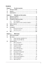
Page 3: ... connectors 2 14 2 6 2 Internal connectors 2 16 2 7 Slot 2 25 Chapter 3 BIOS setup 3 1 BIOS Setup program 3 1 3 2 Main menu 3 2 3 2 1 System Date Day MM DD YYYY 3 2 3 2 2 System Time HH MM SS 3 2 3 3 Advanced menu 3 2 3 3 1 LVDS Configuration 3 2 3 3 2 PCH FW Configuration 3 4 3 3 3 Trusted Computing 3 4 3 3 4 CPU Configuration 3 5 3 3 5 Graphics Configuration 3 6 3 3 6 Power Management 3 6 3 3 7 ...

Page 4: ...PM Configuration 3 13 3 3 19 EZ Flash 3 15 3 3 20 IO Expander Configuration 3 15 3 3 21 Watchdog Timer 3 15 3 4 Hardware Monitor menu 3 16 3 4 1 Smart Fan Mode 3 16 3 4 2 Smart Fan Function 3 16 3 5 Security menu 3 16 3 5 1 Administrator Password 3 16 3 5 2 User Password 3 17 3 5 3 Secure Boot 3 17 3 6 Boot menu 3 18 3 7 Exit menu 3 18 Appendix Notices A 1 Service and Support A 5 ...

Page 5: ...r distributor or sales representative immediately 1 2 Features Intel socket 1700 for 12th Gen Intel Core i9 i7 i5 i3 Pentium and Celeron processors up to 65W Two Dual Channel DDR5 4800 MHz SO DIMMs up to 64GB 4 x SATA 6 0 Gb s 3 x USB 3 2 Gen 2 4 x USB 3 2 Gen 1 6 x USB 2 0 5 x COM ports 1 x PCIe 5 0 x16 slot 1 x M 2 Key E 2230 for WiFi BT devices 1 x M 2 Key M 2242 2260 2280 with PCIe and SATA mo...

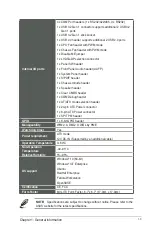
Page 6: ...ansion slots 1 x PCI Express 5 0 x16 slot 1 x M 2 socket 1 Key E 2230 with PCIe and CNVi modes for WiFi BT devices 1 x M 2 socket 3 Key M 2242 2260 2280 with PCIe and SATA modes Supports PCIe bifurcation 16x to 8x 8x Storage 4 x SATA 6 0 Gb s ports Supports RAID 0 1 5 10 1 x M 2 socket 3 Key M 2242 2260 2280 with PCIe and SATA modes LAN Dual Intel Lan 1 x Intel I210AT Co lay I211AT 1 x Intel I225L...

Page 7: ...ker header 1 x Clear CMOS header 1 x COM Debug header 1 x AT ATX mode selection header 1 x 24 pin ATX Power connector 1 x 8 pin ATX Power connector 1 x SPI TPM header GPIO 1 x 8 bit GPIO header Manageability WfM 2 0 DMI 2 0 WOL by PME Watch dog timer Yes Power requirement ATX mode 12V DC IN Supported by an additional cable Operation Temperature 0 60 C Non Operation Temperature 40 85 C Relative Hum...

Page 8: ...R680EI IM A 1 4 ...

Page 9: ...ed wrist strap or touch a safely grounded object or a metal object such as the power supply case to avoid damaging them due to static electricity Hold components by the edges to avoid touching the ICs on them Whenever you uninstall any component place it on a grounded antistatic pad or in the bag that came with the component Before you install or remove any component always remove the AC power by ...

Page 10: ... LAN1_U32G1_5 DP_12 LAN1_U32G2_45 U32G2_C1 U32G1_6 COM2_SEL KBMS 128Mb BIOS LGA1700 LVDS_EDP U32G1_78 Intel R680E Intel i210AT Intel I225LM ALC 897 PCIEX16 G5 CPU_FAN CHA_FAN USB_9 12 DP3 HDMI COM1 PANEL_SW GPIO_CON TPM M 2 WIFI 2280 2260 2242 EATX12V DIS_ME 17 18 15 16 14 4 13 13 19 20 21 22 15 26 27 28 24 23 25 8 9 1 11 12 10 3 2 7 6 4 5 1 2 2 Motherboard layout Place this side towards the rear ...

Page 11: ... pin GPIO_CON 2 17 11 Speaker header 4 pin SPEAKER 2 20 12 System Panel header 10 1 pin F_PANEL 2 19 13 COM1 2 Ring 5V 12V selection jumpers 6 pin COM1_SEL COM2_SEL 2 10 14 DDR5 SO DIMM slots 2 9 15 USB 3 2 Gen 1 connectors 20 1 pin U32G1_78 U32G1_6 2 16 16 USB 2 0 header 10 1 pin USB_213 2 17 17 SATA 6 0Gb s ports 7 pin SATA6G_1 4 2 20 18 Clear CMOS header 2 pin CLRTC 2 13 19 PCI Express 5 0 x16 ...

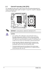
Page 12: ... is shipment transit related Keep the cap after installing the motherboard The manufacturer will process Return Merchandise Authorization RMA requests only if the motherboard comes with the cap on the LGA1200 socket The product warranty does not cover damage to the socket contacts resulting from incorrect CPU installation removal or misplacement loss incorrect removal of the PnP cap 2 3 Central Pr...

Page 13: ...2 5 Chapter 2 Motherboard information 2 3 1 CPU installation 1 2 3 ...

Page 14: ...R680EI IM A 2 6 4 5 ...

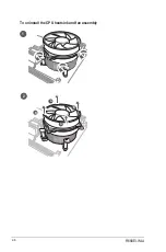
Page 15: ...heatsink and fan assembly installation CAUTION Apply the Thermal Interface Material to the CPU heatsink and CPU before you install the heatsink and fan if necessary To install the CPU heatsink and fan assembly B A A B LGA1200 LGA1700 LGA1800 1 2 3 4 ...

Page 16: ...R680EI IM A 2 8 A B B A To uninstall the CPU heatsink and fan assembly 2 1 ...

Page 17: ...line Dual Inline Memory Module SO DIMM sockets The figure below illustrates the location of the DDR5 SO DIMM sockets Channel Sockets Channel A SO DIMM_B1 Channel B SO DIMM_A1 Installing a DIMM SO DIMM_A1 SO DIMM_B1 R680EI IM A 1 2 To remove a DIMM B A B A A DIMM_B1 DIMM_A1 DIMM_A1 DIMM_B1 Recommended memory configuration ...

Page 18: ...EI IM A 3 12V 2 5V 1 3V Default VCC_PWR_SEL Connector type HEADER 2 x 3p 2 54mm pitch S T 2 COM1 2 Ring 5V 12V selection 6 pin COM1_SEL COM2_SEL Setting Pins 12V 1 2 5V 3 4 Ring Default 5 6 R680EI IM A RI Default 5V 12V COM1_SEL COM2_SEL 1 2 3 4 5 6 RI Default 5V 12V 1 2 3 4 5 6 B A A B Connector type HEADER 2x3p 2 54mm pitch S T ...

Page 19: ... AT_ATX_SEL Connector type HEADER 1x3p 2 54mm pitch S T 4 Disable ME jumper 3 pin DIS_ME This jumper allows you to enable or disable the Intel ME function Set this jumper to pins 1 2 to enable default the Intel ME function and to pins 2 3 to disable it R680EI IM A 2 1 2 3 DIS_ME Disable intel ME function Normal Default Connector type HEADER 1x3p 2 54mm pitch S T ...

Page 20: ...placed The signal is then generated as a chassis intrusion event By default the pin labeled Chassis Signal and Ground are shorted with jumper caps Remove the jumper caps only when you intend to use the chassis intrusion detection feature R680EI IM A PIN 1 5VSB_MB Chassis Signal GND CHASSIS Connector type HEADER 4p K2 2 54mm pitch 6 LVDS eDP Panel Enable Signal Selection header BKLTEN_SEL Pins 1 2 ...

Page 21: ... the boot process and enter BIOS Setup to re enter data NOTE If the steps above do not help remove the onboard battery and move the jumper again to clear the CMOS RTC RAM data After clearing the CMOS reinstall the battery 7 Clear CMOS header 2 pin CLRTC This header allows you to clear the CMOS RTC RAM data of the system setup information such as date time and system passwords R680EI IM A BAT GND C...

Page 22: ...hub LAN port LED indications 6 LAN RJ 45 port This port allows Gigabit connection to a Local Area Network LAN through a network hub ACT LINK LED SPEED LED LAN port ACT LINK LED SPEED LED LAN port Activity Link LED Speed LED Status Description Status Description Off No link OFF 10Mbps connection Orange Linked ORANGE 100Mbps connection Orange Blinking Data activity GREEN 1Gbps connection Orange Blin...

Page 23: ...port is for a USB 3 2 Gen 1 device USB 3 2 Gen 1 devices can only be used for data storage We strongly recommend that you connect USB 3 2 Gen 1 devices to USB 3 2 Gen 1 ports for faster and better performance from your USB 3 2 Gen 1 devices Due to the design of the Intel 300 series chipset all USB devices connected to the USB 2 0 and USB 3 2 Gen 1 ports are controlled by the xHCI controller Some l...

Page 24: ... charging time for USB chargeable devices optimized power efficiency and backward compatibility with USB 2 0 R680EI IM A U32G1_78 U32G1_6 A B A B USB3 5V IntA_P1_SSRX IntA_P1_SSRX GND IntA_P1_SSTX IntA_P1_SSTX GND IntA_P1_D IntA_P1_D GND PIN 1 USB3 5V IntA_P2_SSRX IntA_P2_SSRX GND IntA_P2_SSTX IntA_P2_SSTX GND IntA_P2_D IntA_P2_D 1 LCD panel monitor switch header 2 pin PANEL_SW This 2 pin header i...

Page 25: ...ies with USB 2 0 specification that supports up to 480 Mbps connection speed R680EI IM A USB_213 USB 5V USB_P1 USB_P1 GND NC USB 5V USB_P2 USB_P2 GND PIN 1 4 General purpose input output connector 10 pin GPIO_CON This connector is for a general purpose input output module which allows you to customize the digital signal input output R680EI IM A GPIO1 GPIO3 GPIO5 GPIO7 3V GPIO2 GPIO4 GPIO6 GPIO8 GN...

Page 26: ...I IM A CHA_FAN CPU_FAN CHA FAN PWM CHA FAN IN CHA FAN PWR GND B A GND CPU FAN PWR CPU FAN IN CPU FAN PWM A B 6 SPI TPM header 14 1 pin SPI TPM This header supports a Trusted Platform Module TPM system with a Serial Peripheral Interface SPI allowing you to securely store keys digital certificates passwords and data A TPM system also enhances network security protects digital identities and ensures ...

Page 27: ... activity LED 2 pin HDD_LED This 2 pin header is for the HDD Activity LED Connect the HDD Activity LED cable to this connector The IDE LED lights up or flashes when data is read from or written to the HDD ATX power button soft off button 2 pin PWR_BTN This 2 pin header is for the system power button Reset button 2 pin RESET This 2 pin header is for the chassis mounted reset button for system reboo...

Page 28: ...r is for an LCD monitor that supports Low Voltage Differential Signaling LVDS interface or an internal embedded DisplayPort eDP connection R680EI IM A LVDS_EDP LVDS Signal EDP Signal PIN 1 NC NC NC NC NC LVDS_TX_TD1N LVDS_TX_TD1P LVDS_TX_TB1N LVDS_TX_TB1P GND LVDS_TX_TD0N LVDS_TX_TD0P LVDS_TX_TC0N LVDS_TX_TC0P LVDS_TX_TA0N LVDS_TX_TA0P LCD_VCC GND NC LCD_VCC NC NC NC NC NC LVDS_TX_TCLK1N LVDS_TX_T...

Page 29: ...K_P Key Key Key Key GND S_WIFI_TXP_C S_WIFI_TXN_C GND S_WIFI_RXP S_WIFI_RXN GND CK_WIFI_CLKP CK_WIFI_CLKN GND CK_REQ_M2_WLAN _R S_WAKE _WIFI GND S_CNV_WT_D1_N S_CNV_WT_D1_P GND S_CNV_WT_D0_N S_CNV_WT_D0_P GND S_CNV_WT_CLK_N S_CNV_WT_CLK_P GND 3VSB_WIFI 3VSB_WIFI NC M 2_BT_PCMCLK S_CNV_RF_RESET_N M 2_BT_PCMIN S_XTAL_CLKREQ NC GND NC S_CNV_BRI_RSP Key Key Key Key S_CNV_RGI_DT S_CNV_RGI_RSP S_CNV_BRI...

Page 30: ...is R680EI IM A Ring RTS GND TXD DCD CTS DSR DTR RXD COM3 COM4 COM5 COM2 A B C D PIN 1 PIN 1 DCD TXD GND RTS Ring RXD DTR DSR CTS A B C D Connector type BOX header 2x5p K10 2 0mm pitch 15 Flat panel display brightness connector 5 pin LCD_BLKT_PANEL This connector is for the LVDS eDP panel backlight voltage selection R680EI IM A 12V GND LCD_ENABKLT_CN H_LCD_BL_PWM_SW 5V PIN1 12V GND LCD_ENABKLT_CN N...

Page 31: ...der 10 1 pin AAFP This header is for a chassis mounted front panel audio I O module that supports HD Audio standard Connect one end of the front panel audio I O module cable to this header IMPORTANT We recommend that you connect a high definition front panel audio module to this connector to avail of the motherboard s high definition audio capability If you want to connect a high definition front ...

Page 32: ...olts 5 Volts 5 Volts GND GND GND PSON GND 12 Volts 3 Volts 3 Volts 12 Volts 12 Volts 5V Standby Power OK GND 5 Volts GND 5 Volts GND 3 Volts 3 Volts Pins Signal Pins Signal 1 3 3V out 13 3 3V out 2 3 3V out 14 NC 3 GND 15 GND 4 5V out 16 PSON 5 GND 17 GND 6 5V out 18 GND 7 GND 19 GND 8 NC 20 12V out 9 NC 21 5V out 10 12V in 22 5V out 11 12V in 23 5V out 12 3 3V out 24 GND DC Mode EATXPWR Pins Sign...

Page 33: ...2 25 Chapter 2 Motherboard information 2 7 Slot 1 PCI Express slot This slot supports a PCIe 5 0 x16 graphics card that complies with the PCI Express specification PCIEX16 G5 R680EI IM A ...

Page 34: ...R680EI IM A 2 26 ...

Page 35: ...failed to enter BIOS Setup using the first two options NOTE Using the power button reset button or the Ctrl Alt Del keys to reboot a running operating system can cause damage to your data or system Always shut down the system properly from the operating system IMPORTANT Visit the ASUS website at www asus com to download the latest BIOS file for this motherboard The default BIOS settings for this m...

Page 36: ...you with an overview of the basic system information and allows you to set the system date and the system time 3 2 1 System Date Day MM DD YYYY Allows you to set the system date 3 2 2 System Time HH MM SS Allows you to set the system time 3 3 Advanced menu The Advanced menu items allow you to change the settings for the CPU and other system devices Be cautious when changing the settings of the Adv...

Page 37: ...1 1400x1050 LVDS2 1600x1200 1366x768 1680x1050 1920x1200 1440x900 1600x900 1024x768 1280x800 1920x1080 2048x1536 Inverter Polarity Configuration options Normal Inverted Channel Select Configuration options Dual Channel Single Channel Mode Select Confuguration options JEIDA VESA 6bit VESA 8bit VESA 10bit DIGON enable to LVDS_ON enable T2 Configuration options 0 50 LVDS_ON enable to BLON enable T3 C...

Page 38: ... PCR Bank Configuration options Disabled Enabled SM3_256 PCR Bank Configuration options Disabled Enabled Pending operation Allows you to schedule an operation for security device Configuration options None TPM Clear Your computer will reboot during restart in order to change the state of security device Platform Hierarchy Configuration options Disabled Enabled Storage Hierarchy Configuration optio...

Page 39: ...power Intel SpeedStepTM Allows your system to support more than two frequency ranges Configuration options Disabled Enabled Intel Speed Shift Technology Allows you to enable or disable Intel Speed Shift Technology support When enabled CPPC v2 interface allows hardware controlled P state Configuration options Disabled Enabled The following item appears only when Intel SpeedStep or Intel Speed Shift...

Page 40: ...isplay Allows you to select which of the IGFX PEG Graphics devices should be the primary display or select SG for switchable Gfx Configuration options Auto IGFX PEG Slot Internal Graphics Configuration options Auto Disabled Enabled Auto Keeps IGFX enabled base on the setup options Disabled Disables internal graphics Enabled Enables internal graphics RC6 Render Standby Allows you to enable or disab...

Page 41: ...t the time milliseconds of waiting for link to exit Detect state for enabled ports before assuming there is no device and potentially disabling the port Use the and keys to adjust the value or input the desired value 3 3 8 AMT Configuration This item allows you to configure Intel Active Management Technology parameters AMT BIOS Features Allows you to enable or disable AMT BIOS Features When set to...

Page 42: ...ws you to select COM1 mode Configuration options RS232 RS422 RS485 Serial Port 2 Configuration This item allows you to set parameters of Serial Port 2 COMB Serial Port Allows you to enable or disable the serial port COM Configuration options Disabled Enabled COM2 Control Allows you to select COM2 mode Configuration options RS232 RS422 RS485 Serial Port 3 Configuration This item allows you to set p...

Page 43: ...ptions VT100 VT100Plus VT UTF8 ANSI VT100 ASCII char set VT100Plus Extends VT100 to support color function keys etc VT UTF8 Uses UTF8 encoding to map Unicode chars onto 1 or more bytes ANSI Extended ASCII char set Bits per second Allows you to select serial port transmission speed The speed must be matched on the other side Long or noisy lines may require lower speeds Configuration options 9600 19...

Page 44: ...is is to capture Terminal data Configuration options Disabled Enabled Resolution 100x31 Allows you to enable or disable extended terminal resolution Configuration options Disabled Enabled Putty KeyPad Allows you to select FunctionKey and KeyPad on Putty Configuration options VT100 LINUX XTERMR6 SCO ESCN VT400 COM6 Pci Bus0 Dev0 Func0 Disabled The following items can be configured only when AMT is ...

Page 45: ...s Disabled Enabled Hot Plug Allows you to designate this port as Hot Pluggable Configuration options Disabled Enabled M 2_2 Configuration options Disabled Enabled 3 3 12 VMD setup menu Enable VMD controller This item allows you to disable or enable VMD controller Configuration options Disabled Enabled 3 3 13 Network Stack Configuration Network Stack This item allows you to disable or enable the UE...

Page 46: ...s you to enable or disable USB port Once set to Disabled any USB devices plugged into the connector will not be detected by BIOS or OS Configuration options Disabled Enabled U32G2_4 5 Allows you to enable or disable USB port Once set to Disabled any USB devices plugged into the connector will not be detected by BIOS or OS Configuration options Disabled Enabled U32G1_6 8 Allows you to enable or dis...

Page 47: ...nabled CPU PCIEX16 switch function Configuration options 2x8 1x16 3 3 17 Miscellaneous DMI OPI Configuration DMI Gen3 ASPM Configuration options Disabled Auto ASPM L0s ASPM L1 ASPM L1 ASPM L0sL1 DMI ASPM Configuration options Disabled Auto ASPM L0s ASPM L1 ASPM L1 ASPM L0sL1 PCI Express Configuration DMI Link ASPM Control Allows you to disable or control Active State Power Management on SA side of...

Page 48: ...vent Wake up hour Allows you to enter a natural number within 0 23 for hour For example enter 3 for 3 00 am and 15 for 3 00 pm Wake up minute Allows you to enter a natural number within 0 59 for minute Wake up second Allows you to enter a natural number within 0 59 for second The following items appear when you set Power On By RTC to Weekly event Alarm day of Week Allows you to select the day of t...

Page 49: ...h mode After you press Enter a confirmation message appears Use the left right arrow key to select between Yes or No then press Enter to confirm your choice 3 3 20 IO Expander Configuration This item allows you to configure IO Expander IO Expander GPIO 0 3 Direction Configuration options Output Input Output Value Configuration options High Low IO Expander GPIO 4 7 Direction Configuration options O...

Page 50: ...urity menu The Security menu allows a new password to be created or a current password to be changed The menu also enables or disables the Secure Boot state and lets the user configure the System Mode state 3 5 1 Administrator Password If you have set an administrator password we recommend that you enter the administrator password for accessing the system To set an administrator password 1 Select ...

Page 51: ...Enter 4 Confirm the password when prompted To clear a user password 1 Select the Clear User Password item and press Enter 2 Select Yes from the Warning message window then press Enter 3 5 3 Secure Boot Secure Boot feature is active when Secure Boot is set to Enabled Platform Key PK is enrolled and the system is running in User mode Changing the mode requires platform reset Configuration options Di...

Page 52: ...r BBS boot options Configuration options Disable Link Enabled Enabled Select to accelerate the boot speed Disable Link Select to go back to normal boot speed Boot mode select Configuration options UEFI FIXED BOOT ORDER Priorities Boot Option 1 6 Allows you to set the system boot order Configuration options Hard Disk NVME CD DVD SD USB Device Network Disabled 3 7 Exit menu The items in the Exit men...

Page 53: ...one so far to any of the setup options Discard Changes Allows you to discard changes done so far to any of the setup options Restore Defaults Allows you to restore or load default values for all the setup options Save as User Defaults Allows you to save the changes done so far as User Defaults Restore User Defaults Allows you to restore the User Defaults to all the setup options ...

Page 54: ...d can radiate radio frequency energy and if not installed and used in accordance with the instructions may cause harmful interference to radio communications However there is no guarantee that interference will not occur in a particular installation If this equipment does cause harmful interference to radio or television reception which can be determined by turning the equipment off and on the use...

Page 55: ... ICES 003 B NMB 003 B Déclaration de conformité de Innovation Sciences et Développement économique Canada ISED Le présent appareil est conforme aux CNR d Innovation Sciences et Développement économique Canada applicables aux appareils radio exempts de licence L exploitation est autorisée aux deux conditions suivantes 1 l appareil ne doit pas produire de brouillage et 2 l utilisateur de l appareil ...

Page 56: ...cycling Takeback Services ASUS recycling and takeback programs come from our commitment to the highest standards for protecting our environment We believe in providing solutions for you to be able to responsibly recycle our products batteries other components as well as the packaging materials Please go to http csr asus com english Takeback htm for detailed recycling information in different regio...

Page 57: ...ваниям и другим соответствующим условиям соответствующих директив Подробную информацию пожалуйста смотрите на www asus com support Български С настоящото ASUSTeK Computer Inc декларира че това устройство е в съответствие със съществените изисквания и другите приложими постановления на свързаните директиви Пълният текст на декларацията за съответствие на ЕС е достъпна на адрес www asus com support ...

Page 58: ...City 1F No 15 Lide Rd Beitou Dist Taipei City 112 Taiwan Authorized Representative in Europe ASUS COMPUTER GmbH Address Harkortstrasse 21 23 40880 Ratingen Country Germany Authorized Representative in United Kingdom ASUSTEK UK LIMITED Address 1st Floor Sackville House 143 149 Fenchurch Street London EC3M 6BL England Country United Kingdom ...

Reviews: