background image

ROG STRIX B660-G GAMING WIFI

A-1

Ap

pendix

Appendix

Appendix

Notices

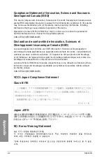
FCC Compliance Information

Responsible Party: Asus Computer International

Address: 48720 Kato Rd., Fremont, CA 94538, USA

Phone / Fax No: (510)739-3777 / (510)608-4555

This device complies with part 15 of the FCC Rules. Operation is subject to the following 

two conditions: (1) This device may not cause harmful interference, and (2) this device must 

accept any interference received, including interference that may cause undesired operation.
This equipment has been tested and found to comply with the limits for a Class B digital 

device, pursuant to part 15 of the FCC Rules. These limits are designed to provide 

reasonable protection against harmful interference in a residential installation. This 

equipment generates, uses and can radiate radio frequency energy and, if not installed 

and used in accordance with the instructions, may cause harmful interference to radio 

communications. However, there is no guarantee that interference will not occur in a 

particular installation. If this equipment does cause harmful interference to radio or television 

reception, which can be determined by turning the equipment off and on, the user is 

encouraged to try to correct the interference by one or more of the following measures:
 - Reorient or relocate the receiving antenna.
 - Increase the separation between the equipment and receiver.
 -  Connect the equipment into an outlet on a circuit different from that to which the receiver 

is connected.

 - Consult the dealer or an experienced radio/TV technician for help.

HDMI Compliance Statement

The terms HDMI, HDMI High-Definition Multimedia Interface, and the HDMI Logo are 

trademarks or registered trademarks of HDMI Licensing Administrator, Inc.

RF exposure warning

This equipment must be installed and operated in accordance with provided instructions and 

the antenna(s) used for this transmitter must be installed to provide a separation distance of 

at least 20 cm from all persons and must not be co-located or operating in conjunction with 

any other antenna or transmitter. End-users and installers must be provide with antenna 

installation instructions and transmitter operating conditions for satisfying RF exposure 

compliance.

Summary of Contents for ROG STRIX B660-G GAMING WIFI

Page 1: ...Motherboard ROG STRIX B660 G GAMING WIFI ...

Page 2: ... MERCHANTABILITY OR FITNESS FOR A PARTICULAR PURPOSE IN NO EVENT SHALL ASUS ITS DIRECTORS OFFICERS EMPLOYEES OR AGENTS BE LIABLE FOR ANY INDIRECT SPECIAL INCIDENTAL OR CONSEQUENTIAL DAMAGES INCLUDING DAMAGES FOR LOSS OF PROFITS LOSS OF BUSINESS LOSS OF USE OR DATA INTERRUPTION OF BUSINESS AND THE LIKE EVEN IF ASUS HAS BEEN ADVISED OF THE POSSIBILITY OF SUCH DAMAGES ARISING FROM ANY DEFECT OR ERROR...

Page 3: ...ation 2 11 2 1 6 ATX power connection 2 12 2 1 7 SATA device connection 2 13 2 1 8 Front I O connector 2 14 2 1 9 Expansion card installation 2 15 2 1 10 Wi Fi moving antenna installation 2 16 2 2 BIOS update utility 2 17 2 3 Motherboard rear and audio connections 2 19 2 3 1 Rear I O connection 2 19 2 3 2 Audio I O connections 2 20 2 4 Starting up for the first time 2 23 2 5 Turning off the comput...

Page 4: ... the electrical outlet you are using contact your local power company If the power supply is broken do not try to fix it by yourself Contact a qualified service technician or your retailer Operation safety Before installing the motherboard and adding devices on it carefully read all the manuals that came with the package Before using the product ensure all cables are correctly connected and the po...

Page 5: ...y and support on RAID Where to find more information Refer to the following sources for additional information and for product and software updates 1 ASUS website The ASUS website www asus com provides updated information on ASUS hardware and software products 2 Optional documentation Your product package may include optional documentation such as warranty flyers that may have been added by your d...

Page 6: ...for memory support list Graphics 1 x DisplayPort 1 x HDMI port Graphics specifications may vary between CPU types Please refer to www intel com for any updates Support 8K 60Hz as specified in DisplayPort 1 4 Support 4K 60Hz as specified in HDMI 2 1 Expansion Slots Intel 12th Gen Processors 1 x PCIe 5 0 x16 slot Intel B660 Chipset 1 x PCIe 3 0 x16 slot supports x4 mode 2 x PCIe 4 0 x1 slots Storage...

Page 7: ...ck output and 113 dB SNR recording input Supports up to 32 Bit 192 kHz playback Audio Features SupremeFX Shielding Technology Savitech SV3H712 AMP Premium audio capacitors Audio cover Due to limitations in HDA bandwidth 32 Bit 192 kHz is not supported for 7 1 Surround Sound audio Back Panel I O Ports 1 x USB 3 2 Gen 2x2 port 1 x USB Type C 1 x USB 3 2 Gen 2 port 1 x Type A 3 x USB 3 2 Gen 1 ports ...

Page 8: ...er with Chassis intrude function 1 x Thermal Sensor header 1 x Thunderbolt header Special Features Extreme Engine Digi 5K Black Metallic Capacitors ASUS Q Design M 2 Q Latch Q DIMM Q LED CPU red DRAM yellow VGA white Boot Device yellow green Q Slot ASUS Thermal Solution M 2 heatsink ASUS EZ DIY BIOS FlashBack button BIOS FlashBack LED CPU Socket lever protector ProCool Pre mounted I O shield SafeS...

Page 9: ...Flash 3 ASUS UEFI BIOS EZ Mode MemTest86 BIOS 256 Mb Flash ROM UEFI AMI BIOS Manageability WOL by PME PXE Operating System Windows 11 64 bit Windows 10 64 bit Form Factor mATX Form Factor 9 6 inch x 9 6 inch 24 4 cm x 24 4 cm Specifications are subject to change without notice Please refer to the ASUS website for the latest specifications MyASUS offers a variety of support features such as helping...

Page 10: ... 2 x SATA 6Gb s cables Miscellaneous 1 x ASUS Wi Fi moving antennas 1 x Cable ties pack 1 x M 2 Rubber package 1 x M 2 Q Latch package 1 x ROG key chain 1 x ROG Strix stickers 1 x ROG Strix thank you card Installation Media 1 x Support DVD Documentation 1 x User guide If any of the above items is damaged or missing contact your retailer ...

Page 11: ...r supply unit Intel LGA 1700 CPU Intel LGA 1700 compatible CPU Fan DDR5 DIMM SATA hard disk drive SATA optical disc drive optional Graphics card optional M 2 SSD module optional 1 Bag of screws The tools and components in the table above are not included in the motherboard package ...

Page 12: ...xii ...

Page 13: ...ity Hold components by the edges to avoid touching the ICs on them Whenever you uninstall any component place it on a grounded antistatic pad or in the bag that came with the component Before you install or remove any component ensure that the ATX power supply is switched off or the power cord is detached from the power supply Failure to do so may cause severe damage to the motherboard peripherals...

Page 14: ...tel B660 DDR5 DIMM_A1 64bit 288 pin module 2280 2260 2280 2260 2242 2242 M 2_2 SOCKET3 M 2_2 SOCKET3 PCIE SATA Optane Memory 4 0 X4 X V M 2_1 SOCKET3 DDR5 DIMM_A2 64bit 288 pin module DDR5 DIMM_B1 64bit 288 pin module DDR5 DIMM_B2 64bit 288 pin module U32G1_C9 Audio HDMI_DP LAN_U32G2_3 U32G1_E12 U32G2X2_C1 M 2 WIFI BATT_CON 256Mb BIOS TPU COM Ethernet Audio Codec M 2_1 SOCKET3 PCIE SATA 4 0 X4 X L...

Page 15: ...8 USB 3 2 Gen 2 Type C Front Panel connector 1 12 9 USB 3 2 Gen 1 header 1 12 10 USB 2 0 headers 1 13 11 Addressable Gen 2 headers 1 14 12 AURA RGB header 1 15 13 Battery connector 1 15 14 Clear CMOS header 1 16 15 COM Port header 1 17 16 Front Panel Audio header 1 17 17 S PDIF Out header 1 18 18 TPM header 1 18 19 System Panel header 1 19 20 Thermal Sensor header 1 20 21 Thunderbolt header 1 20 2...

Page 16: ...ugged before installing the CPU Upon purchase of the motherboard ensure that the PnP cap is on the socket and the socket contacts are not bent Contact your retailer immediately if the PnP cap is missing or if you see any damage to the PnP cap socket contacts motherboard components ASUS will shoulder the cost of repair only if the damage is shipment transit related Keep the cap after installing the...

Page 17: ...e Memory Modules DIMM slots designed for DDR5 Double Data Rate 5 memory modules A DDR5 memory module is notched differently from a DDR DDR2 DDR3 or DDR4 module DO NOT install a DDR DDR2 DDR3 or DDR4 memory module to the DDR5 slot DIMM_A1 DIMM_A2 DIMM_B1 DIMM_B2 Recommended memory configurations ...

Page 18: ...y is dependent on its Serial Presence Detect SPD which is the standard way of accessing information from a memory module Under the default state some memory modules for overclocking may operate at a lower frequency than the vendor marked value For system stability use a more efficient memory cooling system to support a full memory load or overclocking condition Always install the DIMMS with the sa...

Page 19: ...FI 1 7 Chapter 1 3 Expansion slots Unplug the power cord before adding or removing expansion cards Failure to do so may cause you physical injury and damage motherboard components PCIEX1 G4 _1 PCIEX1 G4 _2 PCIEX16 G5 PCIEX16 G3 ...

Page 20: ...to the fan headers Insufficient air flow inside the system may damage the motherboard components These are not jumpers Do not place jumper caps on the fan headers Ensure the cable is fully inserted into the header For water cooling kits connect the pump connector to the AIO_PUMP header AIO_PUMP function support depends on water cooling device Header Max Current Max Power Default Speed Shared Contr...

Page 21: ... B ATX_12V_2 ATX_12V_1 12V DC 12V DC 12V DC 12V DC GND GND GND GND ATX_PWR PIN 1 PIN 1 GND 5 Volts 5 Volts 5 Volts 5 Volts GND GND GND PSON GND 12 Volts 3 Volts 3 Volts 12 Volts 12 Volts 5V Standby Power OK GND 5 Volts GND 5 Volts GND 3 Volts 3 Volts PIN 1 DC_IN DC_IN GND GND C Ensure to connect the 8 pin power plug We recommend that you use a PSU with a higher power output when configuring a syst...

Page 22: ..._2 SOCKET3 M 2_1 SOCKET3 A B Intel 12th Gen Processors M 2_1 slot Key M type 2242 2260 2280 supports PCIe 4 0 x4 mode Intel B660 Chipset M 2_2 slot Key M type 2242 2260 2280 supports PCIe 4 0 x4 mode Intel Rapid Storage Technology supports Intel Optane Memory H Series on PCH attached M 2 slots The M 2 SSD module is purchased separately ...

Page 23: ...A6G_4 GND RSATA_TXP RSATA_TXN GND RSATA_RXN RSATA_RXP GND GND RSATA_TXP RSATA_TXN GND RSATA_RXN RSATA_RXP GND A A B B If you installed SATA storage devices you can create a RAID 0 1 5 and 10 configuration with the Intel Rapid Storage Technology through the onboard Intel B660 chipset Before creating a RAID set refer to the RAID Configuration Guide You can download the RAID Configuration Guide from ...

Page 24: ...X1 GND TX1 TX1 VBUS VBUS TX2 TX2 GND RX2 RX2 GND D D CC2 The USB 3 2 Gen 2 Type C module is purchased separately 9 USB 3 2 Gen 1 header The USB 3 2 Gen 1 header allows you to connect a USB 3 2 Gen 1 module for additional USB 3 2 Gen 1 ports The USB 3 2 Gen 1 header provides data transfer speeds of up to 5 Gb s U32G1_E34 USB3 5V IntA_P1_SSRX IntA_P1_SSRX GND IntA_P1_SSTX IntA_P1_SSTX GND IntA_P1_D ...

Page 25: ...dule for additional USB 2 0 ports The USB 2 0 headers provide data transfer speeds of up to 480 Mb s A B USB 5V USB_P1 USB_P1 GND NC USB 5V USB_P2 USB_P2 GND USB_E12 PIN 1 A USB_E34 B DO NOT connect a 1394 cable to the USB connectors Doing so will damage the motherboard The USB 2 0 module is purchased separately ...

Page 26: ...this board can handle a combined maximum of 500 LEDs Before you install or remove any component ensure that the power supply is switched off or the power cord is detached from the power supply Failure to do so may cause severe damage to the motherboard peripherals or components Actual lighting and color will vary with LED strip If your LED strip does not light up check if the addressable RGB LED s...

Page 27: ...detached from the power supply Failure to do so may cause severe damage to the motherboard peripherals or components Actual lighting and color will vary with LED strip If your LED strip does not light up check if the RGB LED extension cable and the RGB LED strip is connected in the correct orientation and the 12V connector is aligned with the 12V header on the motherboard The LED strip will only l...

Page 28: ... circuit pin 1 2 with a metal object or jumper cap for about 5 10 seconds 3 Plug the power cord and turn ON the computer 4 Hold down the Del key during the boot process and enter BIOS setup to re enter data DO NOT short circuit the pins except when clearing the RTC RAM Short circuiting or placing a jumper cap will cause system boot failure If the steps above do not help remove the onboard button c...

Page 29: ...ule is purchased separately 16 Front Panel Audio header The Front Panel Audio header is for a chassis mounted front panel audio I O module that supports HD Audio Connect one end of the front panel audio I O module cable to this header PORT1L PORT1R PORT2R SENSE_SEND PORT2L AGND NC SENSE1_RETUR SENSE2_RETUR AAFP PIN 1 HD audio compliant pin definition We recommend that you connect a high definition...

Page 30: ...ely 18 TPM header The TPM header allows you to connect a TPM module which securely stores keys digital certificates passwords and data A TPM system also helps enhance network security protect digital identities and ensures platform integrity PIN 1 SPI_TPM S_SPI_TPM_IRQ S_SPI_TPM_CS2 F_BIOS_WP _R GND T_SPI_CLK T_SPI_MOSI VCCSPI S_PLTRST F2_SPI_CS1 _R 3V_SPI F_SPI_CZS0 _R T_SPI_MISO F_SPI_HOLD _R Th...

Page 31: ...from or written to the storage device or storage device add on card System Warning Speaker header SPEAKER The 4 pin header allows you to connect the chassis mounted system warning speaker The speaker allows you to hear system beeps and warnings Power Button Soft off Button header PWRSW The 3 1 pin header allows you to connect the system power button Press the power button to power up the system or...

Page 32: ...the motherboard s component to detect its temperature PIN 1 T_SENSOR SENSOR IN GND The thermal sensor is purchased separately 21 Thunderbolt header The Thunderbolt header allows you to connect an add on Thunderbolt I O card that supports Intel s Thunderbolt Technology allowing you to connect Thunderbolt enabled devices to form a daisy chain configuration PIN 1 FORCE_PWR TB_CIO_PLUG_EVENT SLP_S3 SL...

Page 33: ...ys lit up until the problem is solved CPU RED DRAM YELLOW VGA WHITE BOOT YELLOW GREEN The Q LEDs provide the most probable cause of an error code as a starting point for troubleshooting The actual cause may vary from case to case The add on Thunderbolt I O card and Thunderbolt cables are purchased separately Please visit the official website of your purchased Thunderbolt card for more details on c...

Page 34: ...1 22 Chapter 1 Product Introduction Chapter 1 ...

Page 35: ...gned for LGA1700 socket only DO NOT install a CPU designed for LGA1155 LGA1156 LGA1151 and LGA1200 sockets on the LGA1700 socket ASUS will not cover damages resulting from incorrect CPU installation removal incorrect CPU orientation placement or other damages resulting from negligence by the user Take caution when lifting the load lever ensure to hold onto the load lever when releasing the load le...

Page 36: ...allation Chapter 2 Ensure to remove the CPU Socket lever protector on the lever latch before locking the lever latch under the retention tab Failure to do so may cause damages to your system when installing the cooling system ...

Page 37: ...eatsink and fan assembly Apply Thermal Interface Material to the CPU cooling system and CPU before you install the cooling system if necessary Ensure to remove the CPU Socket lever protector on the lever latch before installing the cooling system failure to do so may cause damages to your system ...

Page 38: ...ditional holes for LGA1200 compatible cooling systems are also available on ASUS Intel 600 series motherboards however we still strongly advise consulting with your cooling system vendor or manufacturer on the compatibility and functionality of the cooling system Push pin type LGA1200 compatible cooling systems cannot be installed to this motherboard ...

Page 39: ...itional holes for LGA1200 compatible cooling systems are also available on ASUS Intel 600 series motherboards however we still strongly advise consulting with your cooling system vendor or manufacturer on the compatibility and functionality of the cooling system If you wish to install an AIO cooler we recommend installing the AIO cooler after installing the motherboard into the chassis ...

Page 40: ...2 6 Chapter 2 Basic Installation Chapter 2 2 1 3 DIMM installation To remove a DIMM ...

Page 41: ...lots if you wish to install an M 2 to another M 2 slot Use a Phillips screwdriver when removing or installing the screws or screw stands mentioned in this section If the thermal pad on the M 2 heatsink becomes damaged and needs to replaced we recommend replacing it with a thermal pad with a thickness of 1 25mm The M 2 is purchased separately 1 Loosen the screws from the M 2 heatsink 2 Lift and rem...

Page 42: ... A optional Install the bundled M 2 rubber pad if you are installing a single sided M 2 storage device DO NOT install the bundled M 2 rubber pads when installing a double sided M 2 storage device The rubber pad installed by default is compatible with double sided M 2 storage devices B Rotate and adjust the M 2 Q latch so that the handle points away from the M 2 slot C Install your M 2 to the M 2 s...

Page 43: ...p only if you wish to install an M 2 to type 2242 B Install the M 2 Q Latch to the M 2 length screw hole you wish to install your M 2 to C Rotate and adjust the M 2 Q latch so that the handle points away from the M 2 slot D Install your M 2 to the M 2 slot E Rotate the M 2 Q Latch clockwise to secure the M 2 in place ...

Page 44: ... Chapter 2 Basic Installation Chapter 2 4 Remove the plastic film from the thermal pads on the bottom of the heatsink 5 Replace the heatsink 6 Secure the heatsink using the screws removed previously 6 8 8 7 ...

Page 45: ...hassis ensuring that its rear I O ports are aligned to the chassis rear I O panel 2 1 5 Motherboard installation 2 Place eight 8 screws into the holes indicated by circles to secure the motherboard to the chassis DO NOT over tighten the screws Doing so can damage the motherboard ...

Page 46: ...2 12 Chapter 2 Basic Installation Chapter 2 2 1 6 ATX power connection Ensure to connect the 8 pin power plug OR AND ...

Page 47: ...ROG STRIX B660 G GAMING WIFI 2 13 Chapter 2 2 1 7 SATA device connection OR ...

Page 48: ...stall USB 3 2 Gen 2 Type C connector To install the front panel connector This connector will only fit in one orientation Push the connector until it clicks into place USB 2 0 AAFP To install USB 2 0 connector To install front panel audio connector USB 3 2 Gen 1 To install USB 3 2 Gen 1 connector ...

Page 49: ...ROG STRIX B660 G GAMING WIFI 2 15 Chapter 2 2 1 9 Expansion card installation To install PCIe x16 cards To install PCIe x1 cards ...

Page 50: ...na connector to the Wi Fi ports at the back of the chassis Ensure that the ASUS Wi Fi moving antenna is securely installed to the Wi Fi ports Ensure that the antenna is at least 20 cm away from all persons The illustration above is for reference only The I O port layout may vary with models but the Wi Fi moving antenna installation procedure is the same for all models ...

Page 51: ...4 Shut down your computer 5 Press the BIOS FlashBack button for three 3 seconds until the BIOS FlashBack LED blinks three times indicating that the BIOS FlashBack function is enabled 6 Wait until the light goes out indicating that the BIOS updating process is completed For more BIOS update utilities in BIOS setup refer to the section Updating BIOS in Chapter 3 Do not unplug portable disk power sys...

Page 52: ...2 18 Chapter 2 Basic Installation Chapter 2 For more information on using the BIOS FlashBack feature please refer to https www asus com support or by scanning the QR code below ...

Page 53: ...3 2 Gen 1 Type A ports 8 USB 3 2 Gen 2 Type A port 9 USB 3 2 Gen 2x2 Type C port 10 USB 3 2 Gen 1 Type C port 11 Audio jacks and Refer to the tables on the next page for LAN port LEDs and audio port definitions We strongly recommend that you connect your devices to ports with matching data transfer rate For example connecting your USB 3 2 Gen 1 devices to USB 3 2 Gen 1 ports for faster and better ...

Page 54: ...connection Activity Link LED Status Description OFF No link GREEN Linked BLINKING Data activity Audio 2 4 5 1 or 7 1 channel configuration Port Headset 2 channel 4 channel 5 1 channel 7 1 channel Light Blue Line In Line In Line In Side Speaker Out Lime Line Out Front Speaker Out Front Speaker Out Front Speaker Out Pink Mic In Mic In Mic In Mic In Orange Center Sub woofer Center Sub woofer Black Re...

Page 55: ...ROG STRIX B660 G GAMING WIFI 2 21 Chapter 2 Connect to 4 channel Speakers Connect to Stereo Speakers Connect to 2 channel Speakers ...

Page 56: ...2 22 Chapter 2 Basic Installation Chapter 2 Connect to 5 1 channel Speakers Connect to 7 1 channel Speakers ...

Page 57: ...n self tests POST While the tests are running the BIOS beeps refer to the BIOS beep codes table or additional messages appear on the screen If you do not see anything within 30 seconds from the time you turned on the power the system may have failed a power on test Check the jumper settings and connections or call your retailer for assistance BIOS Beep Description One short beep VGA detected Quick...

Page 58: ...2 24 Chapter 2 Basic Installation Chapter 2 ...

Page 59: ...re settings such as storage device configuration overclocking settings advanced power management and boot device configuration that are needed for system startup in the motherboard CMOS In normal circumstances the default BIOS settings apply to most conditions to ensure optimal performance DO NOT change the default BIOS settings except in the following circumstances An error message appears on the...

Page 60: ...nly if you failed to enter BIOS Setup using the first two options After doing either of the three options press Delete key to enter BIOS Ensure that a USB mouse is connected to your motherboard if you want to use the mouse to control the BIOS setup program If the system becomes unstable after changing any BIOS setting load the default settings to ensure system compatibility and stability Select th...

Page 61: ...own or reset the system while updating the BIOS to prevent system boot failure 1 Insert the USB flash disk that contains the latest BIOS file to the USB port 2 Enter the Advanced Mode of the BIOS setup program Go to the Tool menu to select ASUS EZ Flash 3 Utility and press Enter 3 Press the Left arrow key to switch to the Drive field 4 Press the Up Down arrow keys to find the USB flash disk that c...

Page 62: ...rt 2 Rename the BIOS file as ASUS CAP or SB660G CAP and copy the renamed BIOS file to a USB flash drive 3 Turn on the system 4 Insert the USB flash drive containing the BIOS file to a USB port 5 The utility automatically checks the devices for the BIOS file When found the utility reads the BIOS file and enters ASUS EZ Flash 3 automatically 6 The system requires you to enter BIOS Setup to recover t...

Page 63: ...es fault tolerance to the entire system Use two new drives or use an existing drive and a new drive for this setup The new drive must be of the same size or larger than the existing drive RAID 5 stripes both data and parity information across three or more hard disk drives Among the advantages of RAID 5 configuration include better HDD performance fault tolerance and higher storage capacity The RA...

Page 64: ...3 6 Chapter 3 BIOS Setup Chapter 3 ...

Page 65: ...particular installation If this equipment does cause harmful interference to radio or television reception which can be determined by turning the equipment off and on the user is encouraged to try to correct the interference by one or more of the following measures Reorient or relocate the receiving antenna Increase the separation between the equipment and receiver Connect the equipment into an ou...

Page 66: ...mité de Innovation Sciences et Développement économique Canada ISED Le présent appareil est conforme aux CNR d Innovation Sciences et Développement économique Canada applicables aux appareils radio exempts de licence L exploitation est autorisée aux deux conditions suivantes 1 l appareil ne doit pas produire de brouillage et 2 l utilisateur de l appareil doit accepter tout brouillage radioélectriq...

Page 67: ...外で使用が禁じられています 法律および規制遵守 本製品は電波法及びこれに基づく命令の定めるところに従い使用してください 日本国外では その国の法律または規制により 本製品の使用ができないことがあります このような国では 本 製品を運用した結果 罰せられることがありますが 当社は一切責任を負いかねますのでご了承 ください Précautions d emploi de l appareil a Soyez particulièrement vigilant quant à votre sécurité lors de l utilisation de cet appareil dans certains lieux les avions les aéroports les hôpitaux les stations service et les garages professionnels ...

Page 68: ...1 by weight in homogenous materials for cadmium except for the exemptions listed in Schedule II of the Rule Vietnam RoHS ASUS products sold in Vietnam on or after September 23 2011 meet the requirements of the Vietnam Circular 30 2011 TT BCT Các sản phẩm ASUS bán tại Việt Nam vào ngày 23 tháng 9 năm2011 trở về sau đều phải đáp ứng các yêu cầu của Thông tư 30 2011 TT BCT của Việt Nam Turkey RoHS AE...

Page 69: ...he WiFi operating in the band 5150 5350MHz shall be restricted to indoor use for the country listed below UK UKCA RF Output table The Radio Equipment Regulations 2017 Intel Wi Fi 6 AX201 Model AX201NGW Function Frequency Maximum Output Power EIRP WiFi 2412 2472 MHz 19 423 dBm 5150 5350 MHz 22 197 dBm 5470 5725 MHz 22 029 dBm 5725 5850 MHz 13 353 dBm Bluetooth 2402 2480 MHz 12 182 dBm For the stand...

Page 70: ...ion of Conformity ASUSTek Computer Inc hereby declares that this device is in compliance with the essential requirements and other relevant provisions of Directive 2014 53 EU Full text of EU declaration of conformity is available at https www asus com support The WiFi operating in the band 5150 5350MHz shall be restricted to indoor use for countries listed in the table below Déclaration simplifiée...

Page 71: ...us com support WiFi ki deluje v pasovnem območju 5150 5350 MHz mora biti v državah navedenih v spodnjem seznamu omejen na notranjo uporabo Declaración de conformidad simplificada para la UE Por la presente ASUSTek Computer Inc declara que este dispositivo cumple los requisitos básicos y otras disposiciones pertinentes de la directiva 2014 53 EU En https www asus com support está disponible el text...

Page 72: ... findes på https www asus com dk support HUG ASUS garanciális információk Az ASUS önkéntes gyártói kereskedelmi garanciát kínál Az ASUS fenntartja magának a jogot hogy értelmezze az ASUS kereskedelmi garanciára vonatkozó rendelkezéseket Ezt a kereskedelmi garanciát az ASUS függetlenül és a törvényes garancia mellett nyújtja és semmilyen módon nem befolyásolja vagy korlátozza a jogi garancia nyújto...

Page 73: ...pravo da tumači odredbe svoje ASUS komercijalne garancije Ova ASUS komercijalna garancija daje se nezavisno kao dodatak zakonskoj pravnoj garanciji i ni ka koji način ne utiče na i ne ograničava prava data pravnom garancijom Za sve informacije o garanciji posetite https www asus com support SW ASUS garantiinformation ASUS erbjuder en frivillig kommersiell tillverkningsgaranti ASUS förbehåller sig ...

Page 74: ...INC Address 1F No 15 Lide Rd Beitou Dist Taipei City 112 Taiwan ASUS COMPUTER INTERNATIONAL America Address 48720 Kato Rd Fremont CA 94538 USA ASUS COMPUTER GmbH Germany and Austria Address Harkortstrasse 21 23 40880 Ratingen Germany ASUSTeK UK LIMITED Address 1st Floor Sackville House 143 149 Fenchurch Street London EC3M 6BL England United Kingdom ...

Reviews: