


Chapter 2: Hardware setup
-1
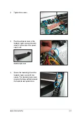
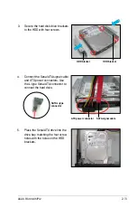
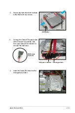
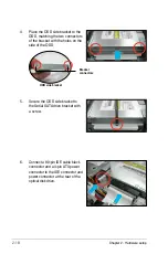
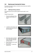
5. Secure the hard drive with four
screws.
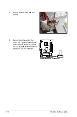
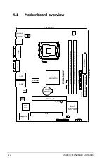
6. Connect the other end of the
Serial ATA signal connector to the
onboard SATA connector labeled
SATA2. Refer to illustration for the
location of SATA2 connector.
P5GC-MR
R
P5GC-MR.SATA.Connectors
SATA1
G
ND
RS
AT
A_
TX
P2
RS
AT
A_
TX
N2
G
ND
RS
AT
A_
RX
N2
RS
AT
A_
RX
P2
G
ND
G
ND
RS
AT
A_
TX
P1
RS
AT
A_
TX
N1
G
ND
RS
AT
A_
RX
N1
RS
AT
A_
RX
P1
G
ND
SATA2
P5GC-MR
R
P5GC-MR.SATA.Connectors
SATA1
G
ND
RS
AT
A_
TX
P2
RS
AT
A_
TX
N2
G
ND
RS
AT
A_
RX
N2
RS
AT
A_
RX
P2
G
ND
G
ND
RS
AT
A_
TX
P1
RS
AT
A_
TX
N1
G
ND
RS
AT
A_
RX
N1
RS
AT
A_
RX
P1
G
ND
SATA2
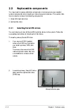
Summary of Contents for RS100-X5 - 0 MB RAM
Page 1: ...RS100 X5 PI2 1U Rackmount Server User s Manual ...
Page 10: ... ...
Page 18: ...Chapter 1 Product introduction 1 ...
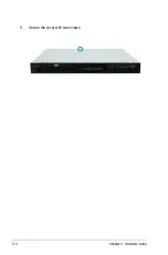
Page 22: ...Chapter 2 Hardware setup 2 3 Secure the cover with two screws ...
Page 58: ...4 12 Chapter 4 Motherboard Information ...
Page 90: ...5 32 Chapter 5 BIOS setup ...


