background image

-10

Chapter 4: Motherboard Information

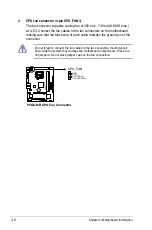
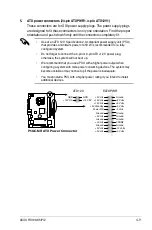
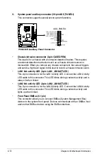
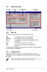
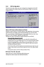
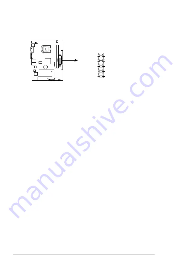
6.. System.panel.auxiliary.connector.(20-pin.AUX_PANEL1)

This connector supports several server system functions.

P5GC-MR

R

P5GC-MR.Auxiliary.Panel.Connector

AUX_PANEL1

I2CDATA_P2

+5VSB

LAN1_LIN

LAN1_LINKACTLED-

GND

+5VSB

I2CCLK_P2

GND

GND

LAN2_LINKACTLED-

LAN2_LIN

CASEOPEN

1

NC

•.

Chassis.Intrusion.connector.(3-pin.CASEOPEN)


This lead is for a chassis with an intrusion detection feature. This requires 

an external detection mechanism such as a chassis intrusion sensor or 

microswitch. When you remove any chassis component, the sensor triggers 

and sends a high-level signal to this lead to record a chassis intrusion event.

•.

LAN1.link.activity.LED.(2-pin.LAN1_LINKACTLED)


This 2-pin connector is for the LAN1 Activity LED. Connect the LAN1 Activity 

LED cable to this connector. This LED blinks during a network activity and is 

always lit when linked.

•.

LAN2.link.activity.LED.(2-pin.LAN2_LINKACTLED)


This 2-pin connector is for the LAN2 Activity LED. Connect the LAN2 Activity 

LED cable to this connector. This LED blinks during a network activity and 

lights up when linked.

•.

Front.Panel.SMBus.(6-1.pin)


This connector allows you to connect SMBus (System Management Bus) 

devices to the system front panel. Devices communicate with an SMBus host 

and/or other SMBus devices using the SMBus interface.

Summary of Contents for RS100-X5 - 0 MB RAM

Page 1: ...RS100 X5 PI2 1U Rackmount Server User s Manual ...

Page 2: ...ion of business and the like even if ASUS has been advised of the possibility of such damages arising from any defect or error in this manual or product Specifications and information contained in this manual ae furnished for informational use only and are subject to change at any time without notice and should not be construed as a commitment by ASUS ASUS assumes no responsibility or liability fo...

Page 3: ... 1 Removing the cover 2 2 2 1 2 Installing the cover 2 3 2 2 Motherboard information 2 5 2 3 Central Processing Unit CPU 2 6 2 3 1 Installing the CPU 2 6 2 3 2 Installing the CPU heatsink 2 8 2 4 System memory 2 10 2 4 1 Overview 2 10 2 4 2 Memory configurations 2 10 2 4 3 Installing a DIMM 2 11 2 4 4 Removing a DIMM 2 11 2 5 Replaceable components 2 12 2 5 1 Installing Serial ATA drives 2 12 2 5 ...

Page 4: ...ting your BIOS 5 2 5 1 1 Creating a bootable floppy disk 5 2 5 1 2 AFUDOS utility 5 3 5 1 3 ASUS CrashFree BIOS 3 utility 5 6 5 2 BIOS setup program 5 8 5 2 1 BIOS menu screen 5 9 5 2 2 Menu bar 5 9 5 2 3 Navigation keys 5 9 5 2 4 Menu items 5 10 5 2 5 Sub menu items 5 10 5 2 6 Configuration fields 5 10 5 2 7 Pop up window 5 10 5 2 8 Scroll bar 5 10 5 2 9 General help 5 10 5 3 Main menu 5 11 5 3 1...

Page 5: ...e Priority 5 27 5 6 2 Boot Settings Configuration 5 28 5 6 3 Security 5 29 5 7 Exit menu 5 31 Chapter 6 Driver installation 6 1 LAN driver installation 6 2 6 1 1 Microsoft Windows Server 6 2 6 1 2 SuSE Linux 6 3 6 1 3 Red Hat Linux 6 4 6 2 Management applications and utilities installation 6 6 6 2 1 Running the support CD 6 6 6 2 2 Drivers menu 6 6 6 2 3 Management Software menu 6 7 6 2 4 Utilitie...

Page 6: ... is encouraged to try to correct the interference by one or more of the following measures Reorient or relocate the receiving antenna Increase the separation between the equipment and receiver Connect the equipment to an outlet on a circuit different from that to which the receiver is connected Consult the dealer or an experienced radio TV technician for help WARNING The use of shielded cables for...

Page 7: ...erver carefully read all the manuals included with the server package Before using the server make sure all cables are correctly connected and the power cables are not damaged If any damage is detected contact your dealer as soon as possible To avoid short circuits keep paper clips screws and staples away from connectors slots sockets and circuitry Avoid dust humidity and temperature extremes Plac...

Page 8: ...e to perform when installing or removing system components 3 Chapter 3 Installation options This chapter describes how to install optional components into the barebone server 4 Chapter 4 Motherboard information This chapter gives information about the motherboard that comes with the server This chapter includes the motherboard layout jumper settings and connector locations 5 Chapter 5 BIOS informa...

Page 9: ...plete a task CAUTION Information to prevent damage to the components when trying to complete a task IMPORTANT Instructions that you MUST follow to complete a task NOTE Tips and information to aid in completing a task Typography Bold text Indicates a menu or an item to select Italics Used to emphasize a word or a phrase Key Keys enclosed in the less than and greater than sign means that you must pr...

Page 10: ... ...

Page 11: ...1 ASUS RS100 X5 PI2 This chapter describes the general features of the chassis kit It includes sections on front panel and rear panel specifications Chapter 1 Product introduction ...

Page 12: ...Server Board Component 1 x 180W Single Power Supply 2 x SATA Cables PCI Express x16 Riser Card ASUS PCIE16 R11 1 01 Front I O Board ASUS FPB R9 USB Board ASUS USB R9 2 x System Fans 2 x 40mm x 40mm x 28mm Accessories 1 x CPU Heatsink with Heat pipe 1 x RS100 X5 PI2 User s Guide 1 x ASUS ASWM 2 0 User s Guide 1 x RS100 X5 PI2 Support CD including ASWM 1 x CA eTrust Anti virus Software CD 1 x Bag of...

Page 13: ... Smart Fan I ASWM2 0 Memory Total Slots 2 Dual Channel Capacity Maximum up to 2GB Memory Type DDR2 667 533 Non ECC Unbuffered DIMM Memory Size 512 MB and 1GB Expansion Slots Total PCI PCI X PCI E Slots 1 Slot Type 1 x PCIe x16 slot at x1 Link Full Height Half Length This slot supports x16 Link only when connected to a PCIe x16 graphics card Storage SATA Controller Intel ICH7 2 x SATA2 300MB s port...

Page 14: ...eTrust 7 1 anti virus software Management Solution Software ASWM2 0 Dimension HH x WW x DD 380mm x 430mm x 43 4mm Net Weight Kg with CPU DRAM and HDD 6 2 kg Power Supply 180W Single Power Supply Environment Operation temperature 10 C 35 C Non operation temperature 40 C 70 C Non operation humidity 20 90 Non condensing ...

Page 15: ...ss LED LAN2 LED LAN1 LED Power LED Reset button Power button 1 4 Rear panel features The rear panel includes the expansion slots system power socket and rear fans The middle part includes the I O shield with openings for the rear panel connectors on the motherboard The ports for the PS 2 keyboard PS 2 mouse USB VGA and Gigabit LAN do not appear on the rear panel if motherboard is not present AC po...

Page 16: ... fans x 2 3 ASUS P5GC MR Server Board 4 Power supply 5 HDD tray 1 hidden and Slim type Optical drive optional 6 HDD tray 2 7 PEB G21 LAN card optional The barebone server does not include a floppy disk drive connect a USB floppy disk drive to any of the USB ports on the front or rear panel if you need to use a floppy disk Only ASUS CD DVD ROMs fit the optical drive bay 2 1 3 5 4 6 7 ...

Page 17: ...the HDD LAN LEDs OFF Blinking ON No LAN connection LAN is transmitting or receiving data LAN connection is present HDD Access LED LAN2 LED LAN1 LED Power LED 1 6 2 LAN RJ 45 LEDs SPEED LED ACT LINK LED Activity Link LED Speed LED Status Description Status Description OFF No link OFF 10 Mbps connection ORANGE Linked ORANGE 100 Mbps connection BLINKING Data activity GREEN 1 Gbps connection ...

Page 18: ...Chapter 1 Product introduction 1 ...

Page 19: ...ASUS RS100 X5 PI2 2 This chapter lists the hardware setup procedures that you have to perform when installing or removing system components Chapter 2 Hardware setup ...

Page 20: ...2 1 1 Removing the cover 1 Use a Phillips screwdriver to remove the screw on the top cover 2 Firmly hold the cover and slide it toward the rear panel for about half an inch until it is disengaged from the chassis 3 Lift the cover from the chassis ...

Page 21: ... RS100 X5 PI2 2 1 2 Installing the cover 1 Position the cover on top of the chassis with the hooks alligned to the side tabs of the chassis 2 Slide the cover toward the front until it snaps in place Side tabs ...

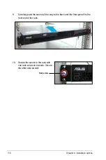
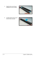
Page 22: ...Chapter 2 Hardware setup 2 3 Secure the cover with two screws ...

Page 23: ... secure the motherboard to the chassis Place this side towards the rear of the chassis Refer to Chapter 4 Motherboard Information for detailed Information Make sure to unplug the power cord before installing or removing the motherboard Failure to do so can cause you physical injury and damage motherboard components ...

Page 24: ... that the PnP cap is on the socket and the socket contacts are not bent Contact your retailer immediately if the PnP cap is missing or if you see any damage to the PnP cap socket contacts motherboard components ASUS shoulders the repair cost only if the damage is shipment transit related Keep the cap after installing the motherboard ASUS will process Return Merchandise Authorization RMA requests o...

Page 25: ... sure that the gold triangle is on the bottom left corner of the socket The socket alignment key should fit into the CPU notch Alignment key Gold triangle mark Load plate A B 2 Press the load lever with your thumb A then move it to the left B until it is released from the retention tab Retention tab Load lever This side of the socket box should face you PnP cap A B To prevent damage to the socket ...

Page 26: ...el Xeon 3000 series processors with the Intel Enhanced Memory 64 Technology EM64T and Enhanced Intel SpeedStep Technology EIST 2 3 2 Installing the CPU heatsink The Intel Xeon 3000 series Core 2 Duo and Conroe L 400 series processors require a specially designed heatsink to ensure optimum thermal condition and performance Use only qualified CPU heatsink assembly To install the CPU heatsink 1 Place...

Page 27: ...of the heatsink mylar cover and evenly attach it to the side of the power supply unit Heatsink mylar cover 4 Secure the heatsink grill and the heatsink mylar cover with two screws The heatsink mylar cover ensures the linear airflow between the heatsink and system fans ...

Page 28: ...DR DIMM socket The figure illustrates the location of the DDR2 DIMM sockets 2 4 2 Memory configurations You may install 512 MB and 1 GB unbuffered non ECC DDR2 533 667 DIMMs into the DIMM sockets P5GC MR R P5GC MR 240 pin DDR2 DIMM Sockets 128 Pins 112 Pins DIMMB1 DIMMA1 Always install DIMMs with the same CAS latency For optimum compatibility we recommend that you obtain memory modules from the sa...

Page 29: ...ips snap back in place and the DIMM is properly seated 2 4 4 Removing a DIMM Follow these steps to remove a DIMM 1 Simultaneously press the retaining clips outward to unlock the DIMM 2 Remove the DIMM from the socket A DDR2 DIMM is keyed with a notch so that it fits in only one direction DO NOT force a DIMM into a socket to avoid damaging the DIMM The DDR2 DIMM sockets do not support DDR DIMMs DO ...

Page 30: ... 2 5 1 Installing Serial ATA drives To install a primary Serial ATA drive 1 If you have an ODD installed remove the ODD bay first before you install a primary SATA disk drive To remove disconnect the ODD cable and power cable then use a screwdriver to remove all two screws You can install up to two 2 Serial ATA hard disk drives to the system Follow the succeeding instructions to install each of th...

Page 31: ... bracket 4 Connect the Serial ATA signal cable and ATX power connectors Use the L type Serial ATA connector to connect the hard drive SATA L type connector ATX power connector SATA signal cable 5 Place the Serial ATA drive into the drive bay matching the four screw holes with the holes on the HDD brackets ...

Page 32: ...for the location of the SATA1 connector P5GC MR R P5GC MR SATA Connectors SATA1 GND RSATA_TXP2 RSATA_TXN2 GND RSATA_RXN2 RSATA_RXP2 GND GND RSATA_TXP1 RSATA_TXN1 GND RSATA_RXN1 RSATA_RXP1 GND SATA2 To install a secondary Serial ATA drive 1 Locate the secondary Serial ATA drive bay between the optical disc drive and power supply unit Secondary SATA drive plate Optical disc drive Power supply unit ...

Page 33: ...our screws HDD bracket HDD bracket 3 Connect the Serial ATA signal cable and ATX power connectors Use the L type Serial ATA connector to connect the hard drive SATA L type connector ATX power connector SATA signal cable 4 Insert the Serial ATA drive into the drive plate as shown ...

Page 34: ... Refer to illustration for the location of SATA2 connector P5GC MR R P5GC MR SATA Connectors SATA1 GND RSATA_TXP2 RSATA_TXN2 GND RSATA_RXN2 RSATA_RXP2 GND GND RSATA_TXP1 RSATA_TXN1 GND RSATA_RXN1 RSATA_RXP1 GND SATA2 P5GC MR R P5GC MR SATA Connectors SATA1 GND RSATA_TXP2 RSATA_TXN2 GND RSATA_RXN2 RSATA_RXP2 GND GND RSATA_TXP1 RSATA_TXN1 GND RSATA_RXN1 RSATA_RXP1 GND SATA2 ...

Page 35: ... then secure it with a screw 2 5 2 Installing optical disk drive optional To install an optical disk drive ODD 1 Connect the 80 pin IDE cable blue connector to the IDE connector onboard 2 Slide in the optical disk drive into the drive slot as shown Optical disk drive slot ODD bracket Optical disk drive optional ...

Page 36: ...cket with the holes on the side of the ODD ODD side bracket Bracket connectors 5 Secure the ODD side bracket to the Serial SATA drive bracket with a screw 6 Connect a 80 pin IDE cable black connector and a 4 pin ATX power connector to the IDE connector and power connector at the rear of the optical disk drive ...

Page 37: ...ASUS RS100 X5 PI2 2 This chapter describes how to install the optional components and devices into the barebone server Chapter 3 Installation options ...

Page 38: ...stem six 6 pieces of inner rail screws and two 2 pieces of rack screws 3 1 1 Attaching the rack ears The bundled rack ears serve as handle when inserting or pulling the server from a rack cabinet To attach rack ears 1 Prepare the bundled pair of rack ears and set of eight 8 screws Pair of rack ears Inner rail screws Rack screws Outer rails Inner rails ...

Page 39: ...nstallation 3 Get one rack ear and match the four screw holes to the screw holes on the chassis Orient the rack ear as shown 4 Secure the rack ear to the chassis with four screws 5 Repeat steps 2 4 to attach the other rack ear 1 Attach the inner rail to the correspoding side of the chassis and secure with three inner rail screws Make sure the rail is oriented as shown ...

Page 40: ...lace three 3 nuts on the front and three at the back Do the same to the corresponding side of the rack Nuts 5 Adjust the length of the outer rail to fit the length of the rack cabinet then fasten the two screws 6 Secure the outer rail with two screws at the front and rear of the rack cabinet 7 Find the corresponding 1U space on the other side of the rack cabinet then repeat steps 5 and 6 to attach...

Page 41: ...th sides Slide the latches on the inner rack rails to the direction indicated below Hold the latches and insert the rear side of the server to the front end of the outer rack rail Make sure that the inner rails are properly aligned with the outer rails ...

Page 42: ...n options 3 10 Secure the server to the rack with one rack screw at one side Secure the other side as well 9 Carefully push the server all the way to the back until the front panel fits the front end of the rack Rack screw ...

Page 43: ... server system in a rack cabinet To attach the long rack ears 1 Prepare the bundled pair of long rack ears and set of twelve 12 screws 2 Locate the six screw holes on each front side of the chassis Select one side for installation 3 Get one long rack ear and match the six screw holes to the screw holes on the chassis Orient the rack ear as shown 4 Secure the rack ear to the chassis with six screws...

Page 44: ...t of space 1U on the rack where you wish to install the server 2 Place three 3 nuts on the front and three at the back Do the same to the corresponding side of the rack Nuts 3 2 2 Attaching the server to the rack cabinet 4 Secure the server to the rack with two rack screws at one side Secure the other side as well ...

Page 45: ...venient way to protect and decorate the front server panel 1 Prepare the bundled pair of front panel connectors and a set of twelve 12 screws 2 Secure the front panel connector to the rack ear 3 Secure the rack ear to the chassis with four screws 4 Repeat steps 2 3 to attach the other rack ear ...

Page 46: ...Chapter 3 Installation options 3 10 5 Align the front cover to the pre installed front cover connectors 6 Carefully attach the front cover to the front cover connectors ...

Page 47: ...RS100 X5 PI2 4 This chapter gives inforamtion about the motherboard that comes with the server This chapter includes the motherboard layout jumper settings and connector locations Chapter 4 Motherboard Info ...

Page 48: ...4cm 9 6in DDR2 DIMM_A1 64 bit 240 pin module DDR2 DIMM_B1 64 bit 240 pin module PCI2 PCIEX1_16 CR2032 3V Lithium Cell CMOS Power EATXPWR CPU_FAN CHA_FAN SATA1 SATA2 USB34 Super I O CLRTC RTM876 660 SB_PWR PRI_IDE AUX_PANEL1 FPANEL1 8Mb BIOS Marvell 8056 Marvell 8056 PS 2KBMS T Mouse B Keyboard USB12 LAN1 VGA1 COM1 LAN2 ATX12V ...

Page 49: ... 0 ports 1 and 2 4 5 7 PS 2 keyboard port purple 4 5 Jumper Page Clear RTC RAM CLRTC1 4 4 Internal connectors Page 1 ICH7 Primary IDE connector 40 1 pin PRI_IDE1 4 6 2 Serial ATA connectors 7 pin SATA1 SATA2 4 7 3 USB connector 10 1 pin USB34 4 7 4 CPU fan connector 4 pin CPU_FAN1 4 8 5 ATX power connectors 24 pin ATXPWR1 4 pin ATX12V1 4 9 6 System panel auxiliary connector 20 pin AUX_PANEL1 4 10 ...

Page 50: ...TC RAM 1 Turn OFF the computer and unplug the power cord 2 Remove the onboard battery 3 Move the jumper cap from pins 1 2 default to pins 2 3 Keep the cap on pins 2 3 for about 5 10 seconds then move the cap back to pins 1 2 4 Re install the battery 5 Plug the power cord and turn ON the computer 6 Hold down the Del key during the boot process and enter BIOS setup to re enter data Except when clear...

Page 51: ... LAN port SPEED LED ACT LINK LED Activity Link LED Speed LED Status Description Status Description OFF No link OFF 10 Mbps connection ORANGE Linked ORANGE 100 Mbps connection BLINKING Data activity GREEN 1 Gbps connection 4 VGA port This port is for a VGA monitor or other VGA compatible devices 5 Serial COM1 port This 9 pin communication port is for pointing devices or other serial devices 6 USB 2...

Page 52: ... disk drives you must configure the second drive as a slave device by setting its jumper accordingly Refer to the hard disk documentation for the jumper settings Pin 20 on the IDE connector is removed to match the covered hole on the Ultra DMA cable connector This prevents incorrect insertion when you connect the IDE cable Use the 80 conductor IDE cable for Ultra DMA 100 66 IDE devices P5GC MR R P...

Page 53: ...GC MR R P5GC MR USB 2 0 Connectors USB34 USB 5V USB_P8 USB_P8 GND NC USB 5V USB_P7 USB_P7 GND 1 2 Serial ATA connectors 7 pin SATA1 SATA2 These connectors are for the Serial ATA signal cables for Serial ATA hard disk drives These connectors are set to IDE mode by default In IDE mode you can connect Serial ATA boot data hard disk drives to these connectors P5GC MR R P5GC MR SATA Connectors SATA1 GN...

Page 54: ...s on the motherboard making sure that the black wire of each cable matches the ground pin of the connector Do not forget to connect the fan cables to the fan connectors Insufficient air flow inside the system may damage the motherboard components These are not jumpers Do not place jumper caps on the fan connectors P5GC MR R P5GC MR CPU Fan Connector CPU_FAN GND 12V CPU FAN IN CPU FAN PWM ...

Page 55: ...t forget to connect the 4 pin or 8 pin ATX 12 V power plug otherwise the system will not boot up We recommend that you use a PSU with a higher power output when configuring a system with more power consuming devices The system may become unstable or may not boot up if the power is inadequate You must install a PSU with a higher power rating if you intend to install additional devices P5GC MR R P5G...

Page 56: ...onent the sensor triggers and sends a high level signal to this lead to record a chassis intrusion event LAN1 link activity LED 2 pin LAN1_LINKACTLED This 2 pin connector is for the LAN1 Activity LED Connect the LAN1 Activity LED cable to this connector This LED blinks during a network activity and is always lit when linked LAN2 link activity LED 2 pin LAN2_LINKACTLED This 2 pin connector is for t...

Page 57: ...s for the HDD Activity LED Connect the HDD Activity LED cable to this connector The IDE LED lights up or flashes when data is read from or written to the HDD System warning speaker Orange 4 pin SPEAKER This 4 pin connector is for the chassis mounted system warning speaker The speaker allows you to hear system beeps and warnings ATX power button soft off button Light Green 2 pin PWRSW This connecto...

Page 58: ...4 12 Chapter 4 Motherboard Information ...

Page 59: ...ASUS RS100 X5 PI2 5 This chapter tells how to change the system settings through the BIOS Setup menus Detailed descriptions of the BIOS parameters are also provided Chapter 5 BIOS Setup ...

Page 60: ... file fails or gets corrupted 3 ASUS Update Updates the BIOS in Windows environment Refer to the corresponding sections for details on these utilities 5 1 1 Creating a bootable floppy disk To create a bootable floppy disk in a DOS environement a Insert a 1 44MB floppy disk into the drive b At the DOS prompt type format A S then press Enter Save a copy of the original motherboard BIOS file to a boo...

Page 61: ...mware Update Utility Version 1 19 ASUS V2 07 03 11 24BB Copyright C 2002 American Megatrends Inc All rights reserved Reading flash done Write to file ok A 1 Copy the AFUDOS utility afudos exe from the motherboard support CD to the bootable floppy disk you created earlier 2 Boot the system in DOS mode then at the prompt type afudos o filename where the filename is any user assigned filename not mor...

Page 62: ...le for the motherboard Save the BIOS file to a bootable floppy disk A afudos iP5GCMRRS ROM Write the BIOS filename on a piece of paper You need to type the exact BIOS filename at the DOS prompt A afudos iP5GCMRRS ROM AMI Firmware Update Utility Version 1 19 ASUS V2 07 03 11 24BB Copyright C 2002 American Megatrends Inc All rights reserved WARNING Do not turn off power during flash BIOS Reading fil...

Page 63: ...AT16 or 32 system file before updating the BIOS To format the USB flash drive to a FAT32 16 system file 1 Insert the USB flash drive to an available USB port 2 From the Windows desktop click Start then select My computer 3 Right click the USB flash drive icon then select Format from the menu 4 From the File system field select FAT32 or FAT16 then click the Start button To update the BIOS file 1 Co...

Page 64: ... to the floppy disk drive 3 The utility displays the following message and automatically checks the floppy disk for the original or updated BIOS file Bad BIOS checksum Starting BIOS recovery Checking for floppy 4 Restart the system after the utility completes the updating process Bad BIOS checksum Starting BIOS recovery Checking for floppy Floppy found Reading file P5GCMRRS ROM Completed Start fla...

Page 65: ...MRRS ROM to one USB port on the system 3 The utility will automatically recover the BIOS It resets the system when the BIOS recovery finished DO NOT shut down or reset the system while updating the BIOS Doing so can cause system boot failure 4 Restart the system after the utility completes the updating process The recovered BIOS may not be the latest BIOS version for this motherboard Visit the ASU...

Page 66: ...ish to enter Setup after POST reboot the system by doing any of the following procedures Restart using the OS standard shut down procedure Press Ctrl Alt Del simultaneously Press the reset button on the system chassis Press the power button to turn the system off then back on Using the power button reset button or the Ctrl Alt Del keys to force reset from a running operating system can cause damag...

Page 67: ... menu screen are the navigation keys for that particular menu Use the navigation keys to select items in the menu and change the settings 5 2 1 BIOS menu screen Some of the navigation keys differ from one screen to another Navigation keys Sub menu items System Time 11 10 19 System Date Tue 10 09 2007 Primary IDE Master Not Detected Primary IDE Slave Not Detected SATA1 Not Detected SATA2 Not Detect...

Page 68: ...he Up Down arrow keys or Page Up Page Down keys to display the other items on the screen 5 2 9 General help At the top right corner of the menu screen is a brief description of the selected item Main menu items System Time 11 10 19 System Date Tue 01 01 2002 Legacy Diskette A 1 44M 3 5 in Primary IDE Master Not Detected Primary IDE Slave Not Detected Third IDE Master Not Detected Third IDE Slave N...

Page 69: ... them Select Screen Select Item Change Option F1 General Help F10 Save and Exit ESC Exit BIOS SETUP UTILITY Main v02 58 C Copyright 1985 2004 American Megatrends Inc Primary IDE Master Device Not Detected Type Auto LBA Large Mode Auto Block Multi sector Transfer M Auto PIO Mode Auto DMA Mode Auto SMART Monitoring Auto 32Bit Data Transfer Enabled Select the type of device connected to the system Sy...

Page 70: ...vice supports this mode and if the device was not previously formatted with LBA mode disabled Configuration options Disabled Auto Block Multi sector Transfer M Auto Enables or disables data multi sectors transfers When set to Auto the data transfer from and to the device occurs multiple sectors at a time if the device supports multi sector transfer feature When set to Disabled the data transfer fr...

Page 71: ...ating system OS that you installed Set to Enhanced Mode if you are using native OS such as Windows 2000 XP Vista Set to Compatible Mode if you are using legacy OS such as Windows ME 98 NT and MS DOS Configuration options Disabled Compatible Mode Enhanced Mode Enhanced Mode Support On S ATA The default setting S ATA allows you to use native OS on Serial ATA and Parallel ATA ports We recommend that ...

Page 72: ...ed CPU specification System Memory Displays the auto detected total system memory Model Name ASUS RS100 X5 PI2 Model ID S0060 ASUS BIOS Version 0108 Build Date 10 12 07 Processor Type Intel R Core TM 2 Duo CPU E4500 2 2GHz Speed 2200 MHz Count 2 System Memory Total 512MB Appropriated 8MB Availabe 504MB Select Screen Select Item Change Option F1 General Help F10 Save and Exit ESC Exit BIOS SETUP UT...

Page 73: ... Inc BIOS SETUP UTILITY Advanced USB Configuration Module Version 2 24 0 F 4 USB Devices Enabled 1 Mouse USB Function Enabled Legacy USB Support Auto USB2 0 Controller Enabled USB2 0 Controller mode HiSpeed BIOS EHCI Hand Off Disabled Options Disabled 2 USB Ports 4 USB Ports USB Function Enabled Allows you to enable a specific number of USB ports or disable the USB function Configuration options D...

Page 74: ... menu show the CPU related information that the BIOS automatically detects Select Screen Select Item Change Option F1 General Help F10 Save and Exit ESC Exit This should be enabled in order to enable or disable the Enhanced Halt State Configure advanced CPU settings Module Version 3D 06 Manufacturer Intel Brand String Intel R Core TM 2 Duo CPU E4500 2 20GHz Frequency 2 20GHz FSB Speed 800MHz Cache...

Page 75: ...efetcher Enabled Allows you to enable or disable the Hardware Prefetcher Disable Feature Configuration options Disabled Enabled Adjacent Cache Line Prefetch Enabled Allows you to enable or disable the Adjacent Cache Line Prefetch Disable Feature Configuration options Disabled Enabled Max CPUID Value Limit Disabled Setting this item to Enabled allows legacy operating systems to boot even without su...

Page 76: ...ings Select an item then press Enter to display the sub menu Select Screen Select Item Change Option F1 General Help F10 Save and Exit ESC Exit v02 58 C Copyright 1985 2004 American Megatrends Inc BIOS SETUP UTILITY Advanced Manual DRAM Frequency Setting or Auto by SPD Advanced Chipset Settings DRAM Frequency Auto Configure DRAM Timing by SPD Enabled Hyper Path 3 Auto DRAM Throttling Threshold Aut...

Page 77: ...to CAS Delay 4 Clocks Controls the latency between the DDR SDRAM active command and the read write command Configuration options 2 Clocks 3 Clocks 4 Clocks 5 Clocks 6 Clocks DRAM RAS Activate to Precharge Delay 15 Clocks Configuration options 4 Clocks 5 Clocks 17 DRAM Clocks 18 DRAM Clocks DRAM Write Recovery Time 4 clocks Configuration options 2 Clocks 3 Clocks 4 Clocks 5 Clocks 6 Clocks Hyper Pa...

Page 78: ...20MB 216MB Fixed Graphic Memory Size 56MB This item selects the size of graphic memory used by fixed mode and appears only when you set the Graphics memory type item to FIX Configuration options 56MB 120MB PEG Buffer Length Auto Sets PCIEX graphics card buffer length Configuration options Auto Long Short Link Latency Auto Sets link latency Configuration options Auto Slow Normal PEG Root Control Au...

Page 79: ...8 IRQ4 2F8 IRQ3 3E8 IRQ4 2E8 IRQ3 Onboard PCIE LAN 8056 A B Enabled Allows you to enable LAN 8056 A LAN 8056 B Configuration options Disabled Enabled LAN 8056 Boot ROM Disabled Allows you to Configure LAN 8056 Boot ROM Configuration options Disabled Enabled BIOS SETUP UTILITY Advanced Configure Win627DHG Super IO Chipset Serial Port1 Address 3F8 IRQ4 Onboard PCIE LAN 8056 A Enabled LAN 8056 Boot R...

Page 80: ...ted Configuration options No Yes Palette Snooping Disabled When set to Enabled the pallete snooping feature informs the PCI devices that an ISA graphics device is installed in the system so that the latter can function correctly Configuration options Disabled Enabled IRQ xx assigned to PCI Device When set to PCI Device the specific IRQ is free for use of PCI PnP devices When set to Reserved the IR...

Page 81: ...tor Add additional tables as per ACPI 2 0 specifications Suspend Mode S1 POS Only Allows you to select the Advanced Configuration and Power Interface ACPI state to be used for system suspend Configuration options S1 POS Only ACPI 2 0 Support Disabled Allows you to enable or disable the Advanced Configuration and Power Interface ACPI 2 0 Support Configuration options Disabled Enabled ACPI APIC Supp...

Page 82: ...tem goes on after an AC power loss When set to Last State the system goes into either off or on state whatever the system state was before the AC power loss Configuration options Power Off Power On Last State Power On By RTC Alarm Disabled Allows you to enable or disable RTC to generate a wake event When this item is set to Enabled the items RTC Alarm Date RTC Alarm Hour RTC Alarm Minute and RTC A...

Page 83: ...PM CPU Smart Fan Control Enabled Chassis Fan Speed RPM 3688RPM Chassis Smart Fan Control Enabled VCORE Voltage 1 328V 3 3V Voltage 3 248V 5V Voltage 5 0170V 12V Voltage 12 355V VBAT Voltage 3 248V CPU Temperature v02 58 C Copyright 1985 2007 American Megatrends Inc Select Screen Select Item Change Option F1 General Help F10 Save and Exit ESC Exit BIOS SETUP UTILITY Power CPU Temperature xxxºC xxxº...

Page 84: ...displays the chassis fan speed in rotations per minute RPM If the fan is not connected to the chassis the specific field shows N A Configuration options Ignored N A Chassis Smart Fan Control Enabled Allows you to enable or disable the ASUS Smart Fan feature that smartly adjusts the fan speeds for more efficient system operation Configuration options Disabled Enabled VCORE Voltage 3 3V Voltage 5V V...

Page 85: ...floppy disk drive Floppy Drive B may appear when you set the CD ROM drive as the first boot device BIOS SETUP UTILITY Main Advanced Power Boot Exit v02 58 C Copyright 1985 2007 American Megatrends Inc 5 6 1 Boot Device Priority BIOS SETUP UTILITY Boot Boot Device Priority 1st Boot Device Removable dev 2nd Boot Device Hard Drive 3rd Boot Device ATAPI CD ROM 1st Boot Device Removable Dev 2nd Boot De...

Page 86: ...ST while booting to decrease the time needed to boot the system When set to Disabled BIOS performs all the POST items Configuration options Disabled Enabled Full Screen Logo Enabled Allows you to enable or disable the full screen logo display feature Configuration options Disabled Enabled Set this item to Enabled to use the ASUS MyLogo2 feature AddOn ROM Display Mode Force BIOS Allows you to set d...

Page 87: ...Installed To set a Supervisor Password 1 Select the Change Supervisor Password item then press Enter 2 From the password box type a password composed of at least six letters and or numbers then press Enter 3 Confirm the password when prompted The message Password Installed appears after you successfully set your password To change the supervisor password follow the same steps as in setting a user ...

Page 88: ...ull Access allows viewing and changing all the fields in the Setup utility Change User Password Select this item to set or change the user password The User Password item on top of the screen shows the default Not Installed After you set a password this item shows Installed To set a User Password 1 Select the Change User Password item and press Enter 2 On the password box that appears type a passw...

Page 89: ...ed off When you select this option a confirmation window appears Select YES to save changes and exit If you attempt to exit the Setup program without saving your changes the program prompts you with a message asking if you want to save your changes before exiting Press Enter to save the changes while exiting Exit Discard Changes Select this option only if you do not want to save the changes that y...

Page 90: ...5 32 Chapter 5 BIOS setup ...

Page 91: ...ASUS RS100 X5 PI2 6 This chapter provides instructions for installing the necessary drivers for different system components Chapter 6 Driver installation ...

Page 92: ...ptical drive The CD automatically displays the Drivers menu if Autorun is enabled in your computer Windows automatically detects the LAN controllers and displays a New Hardware Found window Click Cancel to close this window If Autorun is NOT enabled in your computer browse the contents of the support CD to locate the file ASSETUP EXE from the BIN folder Double click the ASSETUP EXE to run the CD 3...

Page 93: ...ll directory install the LAN driver sh install sh 5 In the next step enter 1 to continue Installation script for sk98lin driver Version xx xx x x Oct 19 2007 C Copyright 2003 2007 Marvell R Add to your trouble report the logfile install log which is located in the DriverInstall directory 1 installation 2 generate patch 3 exit Choose your favorite installation method Please read this carfully This ...

Page 94: ...uctions when installing the Marvell 88E8056 LAN controller base driver for the Red Hat Linux OS The following instructions are for Marvell 88E8056 Linux LAN driver V10 22 4 1 or above Visit http support asus com for the latest Linux LAN driver before continuing the driver installation Building the driver Install first the Kernel Development tools before building the driver from the TAR file To bui...

Page 95: ...ve driver PRESS ANY KEY FOR FURTHER INSTRUCTIONS 7 Press any key to continue Do nothing The sk98lin will be installed NOTE It may happen that the alternative driver will be loaded on the next boot process In this case the Marvell driver _WON T_ be loaded Deactivate driver The alternative driver will be renamed to _skge ko or _sky2 ko All references in the etc modprobe conf file will be changed to ...

Page 96: ...s 6 2 1 Running the support CD Place the support CD to the optical drive The CD automatically displays the Drivers menu if Autorun is enabled in your computer If Autorun is NOT enabled in your computer browse the contents of the support CD to locate the file ASSETUP EXE from the BIN folder Double click the ASSETUP EXE to run the CD 6 2 2 Drivers menu The Drivers menu shows the available device dri...

Page 97: ...gement Software menu displays the available network and server monitoring application Click on an item to install 6 2 4 Utilities menu The Utilities menu displays the software applications and utilities that the motherboard supports Click on an item to install ...

Page 98: ...6 Chapter 6 Driver installation 6 2 5 Contact information Click the Contact tab to display the ASUS contact information You can also find this information on the inside front cover of this user guide ...

Reviews: