5-37
ASUS RS500-E9 Series
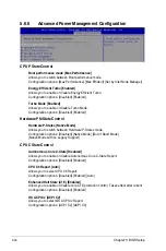
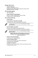
Package C State Control
Package C State [Auto]
Allows you to select Package C State.
Configuration options: [C0/C1 state] [C3 state] [C6(non Retention state)]
[C6(Retention state)] [No Limit] [Auto]
CPU Thermal Management
CPU T State Control
Software Controlled T-States [Disabled]
Allows you to enable or disable Software Controlled T-States.
Configuration options: [Disabled] [Enabled]
CPU - Advanced PM Tuning
Energy Perf BIAS
Power Performance Tuning [OS Controls EPB]
Configuration options: [OS Controls EPB] [BIOS Controls EPB]
The following item appears only when you set
Power Performance Tuning
to
[OS Controls EPB]
.
PECI PCS EPB [OS Controls EPB]
This option controls whether PECI has control over EPB.
Configuration options: [OS Controls EPB] [PECI Controls EPB using PCS]
The following item appears only when you set
Power Performance Tuning
to
[BIOS Controls EPB]
.
ENERGY_PERF_BIAS_CFG Mode [Balanced Performance]
Configuration options: [Performance] [Balanced Performance]
[Balanced Power] [Power]
Dynamic Loadline Switch [Enabled]
Configuration options: [Disabled] [Enabled]
Workload Configuration [UMA]
This option allows optimization for the workload characterization.
Configuration options: [UMA] [NUMA]
Averaging Time Window [17]
This option is used to control the effective window of the average C0 an P0 time.
Configuration options: [0] - [99]
Summary of Contents for RS500-E9 Series
Page 1: ...1U Rackmount Server User Guide RS500 E9 Series RS500 E9 PS4 RS500 E9 RS4 RS500 E9 RS4 U ...
Page 10: ...x ...
Page 25: ...2 5 ASUS RS500 E9 Series 6 Reinstall the air ducts CPU1 CPU socket 1 CPU2 CPU socket 2 ...
Page 51: ...3 5 ASUS RS500 E9 Series 3 2 Rail kit dimensions 589mm 43 6mm 900mm 43 6mm ...
Page 52: ...Chapter 3 Installation Options 3 6 ...
Page 54: ...Chapter 4 Motherboard Information 4 2 4 1 Motherboard layout ...
Page 148: ...6 22 Chapter 6 RAID Configuration ...
Page 155: ...7 7 ASUS RS500 E9 Series 5 Follow the onscreen instructions to complete the installation ...
Page 156: ...7 8 Chapter 7 Driver Installation ...
Page 157: ...Appendix Appendix ...
Page 158: ...Z11PR D16 DC block diagram ...

