


ix
Conventions
To ensure that you perform certain tasks properly, take note of the following symbols used
throughout this manual.
Typography
Bold text
Indicates a menu or an item to select.
Italics
Used to emphasize a word or a phrase.
<Key>
Keys enclosed in the less-than and greater-than
sign means that you must press the enclosed key.
Example: <Enter> means that you must press
the Enter or Return key.
<Key1>+<Key2>+<Key3>
If you must press two or more keys simultaneously,
the key names are linked with a plus sign (+).
Example: <Ctrl>+<Alt>+<Del>
Command
Means that you must type the command
exactly as shown, then supply the required
item or value enclosed in brackets.
Example: At the DOS prompt, type the
command line:
format A:/S
DANGER/WARNING:
Information to prevent injury to yourself when
trying to complete a task.
CAUTION:
Information to prevent damage to the components when
trying to complete a task.
NOTE
: Tips and additional information to help you complete a task.
IMPORTANT
: Instructions that you MUST follow to complete a task.
References
Refer to the following sources for additional information, and for product and software
updates.
1.
ASUS Control Center (ACC) user guide
This manual tells how to set up and use the proprietary ASUS server management
utility.
2.
ASUS websites
The ASUS websites worldwide provide updated information for all ASUS hardware and
software products. Refer to the ASUS contact information.
Summary of Contents for RS500-E9 Series
Page 1: ...1U Rackmount Server User Guide RS500 E9 Series RS500 E9 PS4 RS500 E9 RS4 RS500 E9 RS4 U ...
Page 10: ...x ...
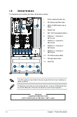
Page 25: ...2 5 ASUS RS500 E9 Series 6 Reinstall the air ducts CPU1 CPU socket 1 CPU2 CPU socket 2 ...
Page 51: ...3 5 ASUS RS500 E9 Series 3 2 Rail kit dimensions 589mm 43 6mm 900mm 43 6mm ...
Page 52: ...Chapter 3 Installation Options 3 6 ...
Page 54: ...Chapter 4 Motherboard Information 4 2 4 1 Motherboard layout ...
Page 148: ...6 22 Chapter 6 RAID Configuration ...
Page 155: ...7 7 ASUS RS500 E9 Series 5 Follow the onscreen instructions to complete the installation ...
Page 156: ...7 8 Chapter 7 Driver Installation ...
Page 157: ...Appendix Appendix ...
Page 158: ...Z11PR D16 DC block diagram ...


