Chapter 1: Product Introduction
1-6
1.4
Front panel features
The barebone server displays a simple yet stylish front panel with easily accessible features.
The power and reset buttons, LED indicators, and USB ports for each Node are located on
the front panel.
Refer to the
1.7.1 Front panel LEDs
section for the LED descriptions.
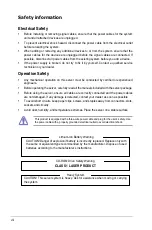
Turn off the system power and detach the power supply before removing or replacing any
system component.
RS500-E8-RS8 V2
RS520-E8-RS12-EV2
1
2
3
4
HDD Bay 1
HDD Bay 5
HDD Bay 2
HDD Bay 6
HDD Bay 3
HDD Bay 7
HDD Bay 4
HDD Bay 8
Slim optical drive (optional)
Refer to 1.7 LED information
Power button
Location button
Reset button
2 x USB 3.0 ports
VGA port
USB 2.0 ports
Reset button
HDD Bay 5
HDD Bay 6
HDD Bay 7
HDD Bay 8
HDD Bay 9
HDD Bay 10
HDD Bay 11
HDD Bay 12
Location button
Power button
Refer to 1.7 LED information
HDD Bay 1
HDD Bay 2
HDD Bay 3
HDD Bay 4
Summary of Contents for RS520-E8-RS12-EV2
Page 1: ...Server User Guide RS520 E8 RS8 V2 RS520 E8 RS12 EV2 ...
Page 12: ...xii ...
Page 56: ...Chapter 2 Hardware Information 2 32 ...
Page 82: ...Chapter 4 Motherboard Information 4 22 ...
Page 106: ...5 24 Chapter 5 BIOS Setup 5 5 IntelRCSetup menu ...
Page 136: ...5 54 Chapter 5 BIOS Setup ...
Page 174: ...6 38 Chapter 6 RAID Configuration ...
Page 202: ...7 28 Chapter 7 Driver Installation ...
Page 203: ...A Contact Information Appendices ...

