ASUS RS520-E8-RS8 V2, RS520-E8-RS12-EV2
4-3
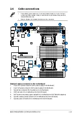
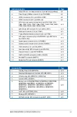
Internal connectors
Page
1.
Serial ATA 6.0 / 3.0 Gbps connector (7-pin SATA6 [Light Blue])
4-8
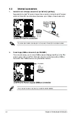
2.
Power Supply SMBus connector (5-pin PSUSMB1)
4-8
3.
USB 2.0 connector (10-1 pin USB56; USB7)
4-9
4.
USB 3.0 connector (20-1 pin USB3_34)
4-9
5.
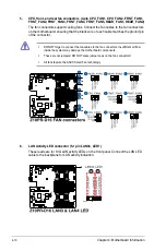
CPU, front, and rear fan connectors (4-pin CPU_FAN1, CPU_
FAN2, FRNT_FAN1, FRNT_FAN2, FRNT_FAN3, FRNT_FAN4,
FRNT_FAN5, REAR_FAN1, REAR_FAN2)
4-10
6.
LAN Activity LED connector (5-1 pin LAN34_LED1)
4-10
7.
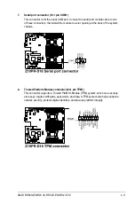
Serial port connector (10-1 pin COM1)
4-11
8.
Trusted Platform Module connector (20-1 pin TPM1)
4-11
9.
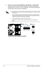
ATX power connectors (24-pin EATXPWR1, 8-pin EATX12V1,
8-pin EATX12V2)
4-12
10.
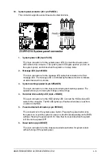
System panel connector (20-1 pin PANEL1)
4-13
11.
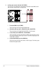
Auxiliary panel connector (20-2 pin AUX_PANEL1)
4-14
12.
VGA connector (10-1 pin VGA_HDR1)
4-15
13.
Hard disk activity LED connector (4-pin HDLED1)
4-15
14.
Chassis Intrusion (2-pin INTRUSION1)
4-16
15.
ISATA & ISSATA connectors (ISATA; ISSATA)
4-16
16.
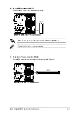
M.2 (NGFF) connector (NGFF1)
4-17
17.
Mezzanine PCI card connector (MEZZ1)
4-17
Onboard LEDs
Page
1.
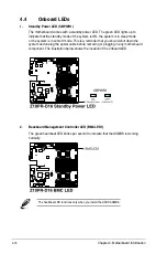
Standby Power LED (SBPWR1)
4-18
2.
Baseboard Management Controller LED (BMCLED1)
4-18
3.
CPU Warning LED (ERRCPU1, ERRCPU2)
4-19
4.
Location LED (LOCLED1)
4-19
5.
Memory error LED (MEMERRA1, MEMERRA2, MEMERRB1,
MEMERRB2, MEMERRC1, MEMERRC2, MEMERRD1,
MEMERRD2, MEMERRE1, MEMERRE2, EMERRF1,
MEMERRF2, MEMERRG1, MEMERRG2, MEMERRH1,
MEMERRH2)
4-20
6.
CATT LED (CATTERR_LED1)
4-20
7.
Message LED (MESLED1)
4-21
8.
OCPLAN Activity LED connector (4-pin OCP_LED1)
4-21
Summary of Contents for RS520-E8-RS12-EV2
Page 1: ...Server User Guide RS520 E8 RS8 V2 RS520 E8 RS12 EV2 ...
Page 12: ...xii ...
Page 56: ...Chapter 2 Hardware Information 2 32 ...
Page 82: ...Chapter 4 Motherboard Information 4 22 ...
Page 106: ...5 24 Chapter 5 BIOS Setup 5 5 IntelRCSetup menu ...
Page 136: ...5 54 Chapter 5 BIOS Setup ...
Page 174: ...6 38 Chapter 6 RAID Configuration ...
Page 202: ...7 28 Chapter 7 Driver Installation ...
Page 203: ...A Contact Information Appendices ...

