

Chapter 4: Motherboard Information
4-14
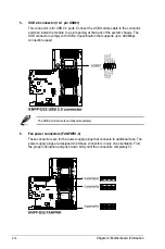
5.
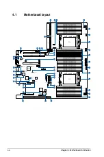
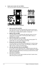
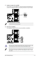
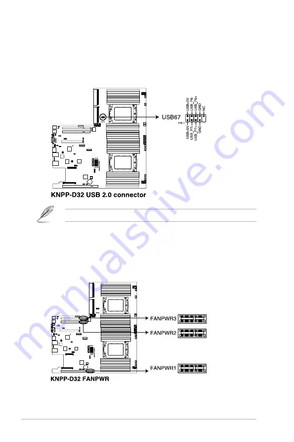
USB 2.0 connector (10-1 pin USB67)
This connector is for USB 2.0 ports. Connect the USB module cable to the connector,
and then install the module to a slot opening at the back of the system chassis. The
USB connectors comply with USB 2.0 specification that supports up to 480 Mbps
connection speed.
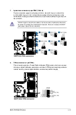
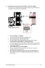
6.
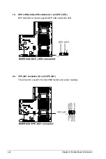
Fan power connectors (FANPWR1-3)
These connectors are for the power supply plugs that connects to additional fans. The
power supply plugs are designed to fit these connectors in only one orientation. Find
the proper orientation and push down firmly until the connectors completely fit.
The USB port module is purchased separately.
Summary of Contents for RS700A-E9-RS12
Page 1: ...1U Rackmount Server User Guide RS700A E9 Series RS700A E9 RS4 RS700A E9 RS12 ...
Page 70: ...Chapter 4 Motherboard Information 4 2 4 1 Motherboard layout ...
Page 92: ...Chapter 4 Motherboard Information 4 24 ...
Page 136: ...6 10 Chapter 6 Driver Installation ...
Page 138: ...A 2 Appendix KNPP D32 block diagram ...
Page 144: ...A 8 Appendix ...


