background image

ASUS KGN(M)H-D16

4-13

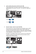
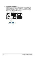
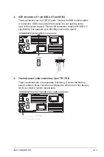
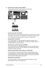
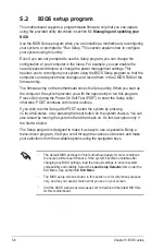
2.  USB connectors (5-1 pin USB3; A-Type USB4)

These connectors are for USB 2.0 ports. Connect the USB module cables 

to connectors USB3, then install the modules to a slot opening at the 

back of the system chassis. These USB connectors comply with USB 2.0 

specification that supports up to 480 Mbps connection speed.

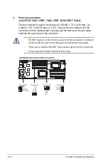
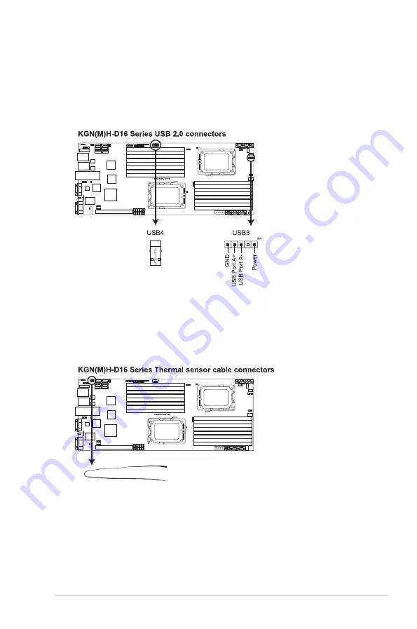
3.  Thermal sensor cable connectors (3-pin TR1, TR2)

These connectors are for temperature monitoring. Connect the thermal 

sensor cables to these connectors and place the other ends to the devices, 

which you want to monitor temperature.

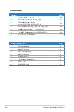
Summary of Contents for RS700DA-E6/PS4

Page 1: ...RS700DA E6 PS4 RS704DA E6 PS4 1U Rackmount Server User Guide ...

Page 2: ...on of business and the like even if ASUS has been advised of the possibility of such damages arising from any defect or error in this manual or product Specifications and information contained in this manual ae furnished for informational use only and are subject to change at any time without notice and should not be construed as a commitment by ASUS ASUS assumes no responsibility or liability for...

Page 3: ...essing Unit CPU 2 3 2 2 1 Installing the CPU 2 3 2 2 2 Installing the CPU heatsink and airduct 2 6 2 3 System memory 2 7 2 3 1 Overview 2 7 2 3 2 Memory Configurations 2 8 2 3 3 Installing a DIMM 2 10 2 3 4 Removing a DIMM 2 10 2 4 Hard disk drives 2 11 2 5 Expansion slot 2 13 2 5 1 Installing an expansion card to the riser card bracket 2 13 2 5 2 Configuring an expansion card 2 14 2 6 Cable conne...

Page 4: ...Info 4 1 Motherboard layout 4 2 4 2 Jumpers 4 6 4 3 Connectors 4 11 4 3 1 Rear panel connectors 4 11 4 3 2 Internal connectors 4 12 Chapter 5 BIOS setup 5 1 Managing and updating your BIOS 5 2 5 1 1 ASUS EZ Flash 2 utility 5 2 5 1 2 BUPDATER utility 5 3 5 1 3 ASUS CrashFree BIOS 3 utility 5 5 5 2 BIOS setup program 5 6 5 2 1 BIOS menu screen 5 7 5 2 2 Menu bar 5 7 5 2 3 Navigation keys 5 7 5 2 4 M...

Page 5: ...y 5 31 5 7 2 Hard Disk Drives CDROM Drives 5 31 5 7 3 Boot Settings Configuration 5 32 5 7 4 Security 5 33 5 8 Tools menu 5 35 5 9 Exit menu 5 36 Chapter 6 RAID configuration 6 1 Setting up RAID 6 2 6 1 1 RAID definitions 6 2 6 1 2 Installing hard disk drives 6 2 6 1 3 Setting the RAID item in BIOS 6 3 6 2 FastBuild Utility 6 4 6 2 1 Creating a RAID set 6 5 6 2 2 Deleting a RAID set 6 11 6 2 3 Vie...

Page 6: ...Gen2 Channel Adapter driver installation For RS704DA E6 PS4 only 7 22 7 5 1 Windows operating system 7 22 7 5 2 Red Hat Enterprise Linux OS 7 26 7 6 Management applications and utilities installation 7 29 7 6 1 Running the support DVD 7 29 7 6 2 Drivers menu 7 29 7 6 3 Utilities menu 7 30 7 6 4 Make disk menu 7 30 7 6 5 Contact information 7 30 Contents ...

Page 7: ...the user is encouraged to try to correct the interference by one or more of the following measures Reorient or relocate the receiving antenna Increase the separation between the equipment and receiver Connect the equipment to an outlet on a circuit different from that to which the receiver is connected Consult the dealer or an experienced radio TV technician for help Canadian Department of Communi...

Page 8: ...efore operating the server carefully read all the manuals included with the server package Before using the server make sure all cables are correctly connected and the power cables are not damaged If any damage is detected contact your dealer as soon as possible To avoid short circuits keep paper clips screws and staples away from connectors slots sockets and circuitry Avoid dust humidity and temp...

Page 9: ...onnectors 5 Chapter 5 BIOS information This chapter tells how to change system settings through the BIOS Setup menus and describes the BIOS parameters 6 Chapter 6 RAID configuration This chapter tells how to change system settings through the BIOS Setup menus Detailed descriptions of the BIOS parameters are also provided 7 Chapter 7 Driver installation This chapter provides instructions for instal...

Page 10: ...emphasize a word or a phrase Key Keys enclosed in the less than and greater than sign means that you must press the enclosed key Example Enter means that you must press the Enter or Return key Key1 Key2 Key3 If you must press two or more keys simultaneously the key names are linked with a plus sign Example Ctrl Alt Del Command Means that you must type the command exactly as shown then supply the r...

Page 11: ...ASUS RS700DA E6 PS4 RS704DA E6 PS4 This chapter describes the general features of the server including sections on front panel and rear panel specifications Chapter 1 Product introduction ...

Page 12: ...contact your retailer xxS0xxxxxxxx RS700DA E6 PS4 Model Name RS700DA E6 PS4 RS704DA E6 PS4 Chassis ASUS R12C 1U Rackmount Chassis Motherboard 2 x ASUS KGNH D16 Server Board 2 x ASUS KGMH D16 QDR Server Board Component 1 x 1400W Easy Swap Single Power Supply 4 x Hot swap 3 5 HDD trays by region 1 x SAS SATA2 Backplane ASUS BP4LX R12C 2 x PCI Riser Card ASUS RE16R R12B 2 x Front I O Board ASUS FPB A...

Page 13: ...o 256GB RDIMM per Node Maximum up to 64GB UDIMM per Node Memory Type DDR3 800 1066 1333 UDIMM with ECC non ECC DDR3 800 1066 1333 RDIMM Memory Size 1GB 2GB 4GB 8GB and 16GB RDIMM 1GB 2GB and 4GB UDIMM Expansion Slots Total PCI PCI X PCI E Slots 1 per Node Slot Type 1 x PCI E 2 0 x16 slot x16 link Low profile HL per Node Storage SATA Controller AMD SP5100 6 x SATA2 300MB s ports PROMISE RAID for Li...

Page 14: ...indows Server 2003 R2 Enterprise 32 64 bit RedHat Enterprise Linux AS5 0 32 64 bit SuSE Linux Enterprise Server 10 32 64 bit Subject to change without any notice Anti virus Software Optional CA eTrust 7 1 anti virus software Management Solution Out of Band Remote Hardware Optional ASMB4 iKVM for KVM over IP support Software ASUS ASWM 2 0 Dimension HH x WW x DD 712mm x 444mm x 43 6mm 1U Net Weight ...

Page 15: ...fer to section 1 7 1 Front panel LEDs for the LED descriptions Turn off the system power and detach the power supply before removing or replacing any system component Hot swap HDD bays Rack screw Rack screw Hot swap HDD bays USB port LAN2 LED HDD Access LED LAN1 LED Message LED Power button Location switch Reset button Location LED Power LED USB port LAN2 LED HDD Access LED LAN1 LED Message LED Po...

Page 16: ...el The ports for the USB VGA and Gigabit LANs do not appear on the rear panel if the motherboards are not present These ports are for ASUS ASMB4 iKVM controller cards only VGA port Power supply fan Power cord connector USB ports LAN port 1 Serial port LAN port 3 LAN port 2 InfiniBand port RS704DA E6 PS4 only VGA port USB ports LAN port 1 Serial port LAN port 3 LAN port 2 InfiniBand port RS704DA E6...

Page 17: ...16 server board RS700DA E6 PS4 ASUS KGMH D16 QDR server board RS704DA E6 PS4 4 System fans 5 SATA SAS backplane hidden 6 7 Hot swap HDD tray 1 2 Connect to SATA port 1 2 of Left System 8 9 Hot swap HDD tray 3 4 Connect to SATA port 1 2 of Right System 10 Front I O boards hidden WARNING HAZARDOUS MOVING PARTS KEEP FINGERS AND OTHER BODY PARTS AWAY 9 5 1 2 3 6 7 8 10 2 3 4 10 Turn off the system pow...

Page 18: ...t ASMB4 iKVM installed CPU over heated 2 With ASMB4 iKVM installed a hardware monitor event is indicated Location LED OFF Normal status ON Location switch is pressed Press the location switch again to turn off LAN LEDs OFF No LAN connection Blinking LAN is transmitting or receiving data ON LAN connection is present 1 7 2 LAN RJ 45 LEDs ACT LINK LED SPEED LED Status Description Status Description O...

Page 19: ...r Fail Status LED Green Light ON Power ON Detection HDD Present Red Light ON RAID HDD Failed HDD plug in ready but detection error Green Red Blinking RAID Rebuilding OFF HDD Not Found HDD Activity LED Green Blinking Data Read Write to HDD HDD Power Fail Status LED Green Red HDD Activity LED Green ...

Page 20: ...Chapter 1 Product introduction 1 10 ...

Page 21: ...ASUS RS700DA E6 PS4 RS704DA E6 PS4 This chapter lists the hardware setup procedures that you have to perform when installing or removing system components Chapter 2 Hardware setup ...

Page 22: ... the cover from the chassis 4 To recover the rear cover reverse step 1 to 3 1 Loosen the two thumbscrews on the rear panel to release the rear cover from the chassis Front side screw Thumbscrews 2 1 Chassis cover Removing the rear cover A protection film is pre attached to the system cover before shipping Please remove the protection film before turning on the system for proper heat dissipation ...

Page 23: ...s motherboard components ASUS shoulders the repair cost only if the damage is shipment transit related Keep the cap after installing the motherboard ASUS will process Return Merchandise Authorization RMA requests only if the motherboard comes with the cap on the Socket 1944 The product warranty does not cover damage to the socket contacts resulting from incorrect CPU installation removal or mispla...

Page 24: ...t the load plate with your thumb and forefinger to a 100º angle 5 Remove the PnP cap from the CPU socket A B Retention tab Load lever 3 4 Load plate PnP cap 5 The CPU fits in only one correct orientation DO NOT force the CPU into the socket to prevent bending the connectors on the socket and damaging the CPU 6 Position the CPU over the socket ensuring that the gold triangle is on the bottom right ...

Page 25: ...sed area of the CPU that the heatsink will be in contact with ensuring that it is spread in an even thin layer Some heatsinks come with pre applied Thermal Interface Material If so skip this step 7 Close the load plate A then push the load lever B until it snaps into the retention tab A B ...

Page 26: ...d When the four screws are attached tighten them one by one to completely secure the heatsink 2 2 2 Installing the CPU heatsink and airduct To install the CPU heatsink 1 Place the heatsink on top of the installed CPU ensuring that the four fasteners match the holes on the motherboard Tighten the four heatsink screws in a diagonal sequence A B B A ...

Page 27: ... E6 PS4 RS704DA E6 PS4 2 3 System memory 2 3 1 Overview The motherboard comes with sixteen 16 Double Data Rate 3 DDR3 Dual Inline Memory Modules DIMM sockets The figure illustrates the location of the DDR3 DIMM sockets ...

Page 28: ...e Rank Dual Ranks CPU 1 Configuration A2 A1 B2 B1 C2 C1 D2 D1 2 DIMMs 4 DIMMs 6 DIMMs 8 DIMMs CPU 1 2 Configuration A2 A1 B2 B1 C2 C1 D2 D1 E2 E1 F2 F1 G2 G1 H2 H1 2 DIMMs 4 DIMMs 6 DIMMs 8 DIMMs 10 DIMMs 12 DIMMs 14 DIMMs 16 DIMMs For RDIMM Single Rank Dual Ranks Quad Ranks CPU 1 Configuration A2 A1 B2 B1 C2 C1 D2 D1 2 DIMMs 4 DIMMs 6 DIMMs 8 DIMMs CPU 1 2 Configuration A2 A1 B2 B1 C2 C1 D2 D1 E2...

Page 29: ...MMs when installing less than or equal to four DIMMs install them to the blue slots in the order of DIMM_A2 DIMM_C2 DIMM_B2 DIMM_D2 For CPU1 CPU2 install DIMMs to the blue slots in the order of DIMM_A2 DIMM_E2 DIMM_C2 DIMM_G2 For Quad Rank DIMMs when installing more than four DIMMs install them to the blue slots in the order of DIMM_A2 DIMM_C2 DIMM_B2 DIMM_D2 DIMM_A1 DIMM_C1 DIMM_B1 DIMM_D1 For CP...

Page 30: ... DIMM socket by pressing the retaining clip outward 2 Align a DIMM on the socket such that the notch on the DIMM matches the DIMM slot key on the socket A DIMM is keyed with a notch so that it fits in only one direction DO NOT force a DIMM into a socket in the wrong direction to avoid damaging the DIMM Ensure to unplug the power supply before adding or removing DIMMs or other system components Fai...

Page 31: ... 1 Release a drive tray by pushing the spring lock to the right then pulling the tray lever outward The drive tray ejects slightly after you pull out the lever 2 Firmly hold the tray lever and pull the drive tray out of the bay spring lock 3 Take note of the drive tray holes Each side has three holes to fit different types of hard disk drives Use two screws on each side to secure the hard disk dri...

Page 32: ...ray edge protrudes 6 Push the tray lever until it clicks and secures the drive tray in place The drive tray is correctly placed when its front edge aligns with the bay edge 7 Repeat steps 1 to 6 if you wish to install a second SATAII SAS drive When installed the SATAII SAS connector on the drive connects to the SATAII SAS interface on the backplane ...

Page 33: ...hold the riser card bracket and then pull it up to detach it from the PCI Express x16 slot on the motherboard 2 Place the riser card bracket on a flat and stable surface and then remove the screw from the slot bay PCI Express x16 slot 3 Install a PCI Express x16 card to the bracket as shown and then secure the card with a screw 4 Press the riser card bracket until the golden connectors completely ...

Page 34: ...l the software drivers for the expansion card These IRQs are usually available for ISA or PCI devices Standard Interrupt assignments IRQ Priority Standard function 0 1 System Timer 1 2 Keyboard Controller 2 Programmable Interrupt 4 12 Communications Port COM1 5 13 6 14 Floppy Disk Controller 7 15 8 3 System CMOS Real Time Clock 9 4 ACPI Mode when used 10 5 IRQ Holder for PCI Steering 11 6 IRQ Hold...

Page 35: ...wer connector from power supply to motherboard 2 4 pin proprietary power connector from motherboard to backplane board 3 System fan connectors from motherboard FRNT_FAN1 FRNT_FAN2 FRNT_FAN3 and FRNT_FAN4 to system fans 4 USB connector from motherboard to front I O board via backplane board 5 Panel connector from motherboard to front I O board via backplane board 6 SATA connectors from motherboard ...

Page 36: ...M optional 4 ASUS PIKE Riser card optional Ensure that the system is turned off before removing any components 2 7 1 Replacing system fans 2 Lift the fan and then set aside 3 Repeat step 1 to 2 to uninstall the other system fans To reinstall the system fans 1 Insert the fan to the fan cage The airflow directional arrow on the fan side should point towards the system rear panel 2 Connect the system...

Page 37: ...fans to ensure proper fan installation as shown in the right figure 2 7 2 Replacing power supply units Follow the steps below to replace the failed power supply unit PSU To remove the failed PSU 1 Lift up the PSU lever 3 Firmly pull the failed PSU out of the server chassis 2 Hold the PSU lever and press the PSU latch ...

Page 38: ...rd optional Follow the steps below to install an optional ASMB4 series management board on your motherboard 3 Insert the LAN cable plug to the LAN3 port for server management 1 Locate the BMC_FW1 header on the motherboard 2 Orient and press the ASMB4 management card in place ...

Page 39: ... riser card bracket then pull it up to detach it from the PCI Express x16 slot on the motherboard 2 Locate the two screws on the riser card bracket then remove the screws from the bracket 3 Locate the two screw holes on the PIKE riser card 4 For PIKE 1064E RAID card secure the riser card to the bracket with two screws For PIKE 1078 2008 and 2008 IMR cards secure only one screw as shown in the righ...

Page 40: ...ompletely seated on the slot For PIKE 1078 2008 and 2008 IMR cards ensure the heatsink latch is completely hooked to the edge of the card slot 6 For PIKE 1078 2008 and 2008 IMR cards secure the PIKE card through the screw hole of the riser card to the card bracket 7 For PIKE 1078 SAS RAID card snap the i Button into the i Button slot on the PIKE raiser card ...

Page 41: ...ket to the PCI Express x16 slot on the motherboard 12 Press the riser card bracket until the golden fingers completely fit the slot and the bracket aligns with the rear panel 8 Connect the SGPIO cable pre installed to the barebone server to the SGPIO connector on the PIKE Riser card 9 Remove the SATA SAS cables from the onboard SATA1 2 connectors ...

Page 42: ...Chapter 2 Hardware setup 2 22 ...

Page 43: ...ASUS RS700DA E6 PS4 RS704DA E6 PS4 This chapter describes how to install the optional components and devices into the barebone server Chapter 3 Installation options ...

Page 44: ...irs of rack rails for the rack Nut and bolt type screws and one pair of server latches Nuts and screws Front rack rails Rear rack rails 3 1 1 Attaching the fixing latches to the server Refer to the image below for the locations to attach the two fixing latches to the two sides of the server with four screws Fixing latch ...

Page 45: ...ack slots 7 Secure the front end of the rail with two rack screws as shown in the right figure 8 Secure the rear end of the rail with two rack screws as shown in the right figure 9 Fasten the eight screw you secure in step 2 as shown in the right figure 10 Repeat steps 6 to 9 to assemble and attach the rack rail on the other side 3 Select one unit of space 1U on the rack where you want to install ...

Page 46: ...rails and then push the server all the way to the depth of the rack To uninstall the server from the rack 1 Loosen the rack screws that secured the server to the rack 2 Pull the server from the rack Remember to press the latches on both sides to release the server from the rack 2 Tighten the two rack screws to secure the server in place ...

Page 47: ...ack Nut and bolt type screws 3 2 1 Attaching the rails to the server To attach the server rails 1 Attach the front end of the server rail to the side of the chassis matching each of the three hooks to the holes on the rail Then slide the rail toward the front panel until it locks in place Rack rails Front end Rear end Nuts and screws 2 Secure the front end of the server rail to the side of the cha...

Page 48: ...it of space 1U on the rack where you want to install the barebone server 2 Install the nuts on the holes of the 1U space on the rack front 3 Install the nuts on the holes of the 1U space on the corresponding rack rear 4 Measure the depth of the rack to determine the length of the rack rails 5 Measure the rack rail when assembled to ensure that it fits the rack 6 Position the rack rail to the 1U sp...

Page 49: ...he rack rails then push the server all the way to the depth of the rack 2 Tighten the two rack screws to secure the server in place To uninstall the server from the rack 1 Loosen the rack screws that secured the server to the rack 2 Pull the server from the rack Remember to press the latches on both sides to release the server from the rack ...

Page 50: ...Chapter 3 Installation options 3 8 ...

Page 51: ...ASUS RS700DA E6 PS4 RS704DA E6 PS4 This chapter includes the motherboard layout and brief descriptions of the jumpers and internal connectors Chapter 4 Motherboard Info ...

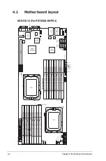
Page 52: ...Chapter 4 Motherboard information 4 2 4 1 Motherboard layout KGNH D16 For RS700DA E6 PS4 ...

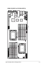
Page 53: ...ASUS RS700DA E6 PS4 RS704DA E6 PS4 4 3 KGMH D16 QDR For RS704DA E6 PS4 ...

Page 54: ... Video Graphics Adapter port 4 11 7 Location LED 4 11 8 Serial COM1 port 4 11 Jumpers Page 1 Clear RTC RAM CLRTC1 4 6 2 VGA controller setting 3 pin VGA_SW1 4 7 3 DDR3 voltage control setting 4 pin LVDDR3_SEL1 LVDDR3_SEL2 4 7 4 LAN controller setting 3 pin LAN_SW1 LAN_SW2 4 8 5 Chassis intrusion connector 2 pin CHASSIS 4 8 6 Force BIOS recovery setting 3 pin RECOVERY1 4 9 7 IPMI setting 3 pin IPMI...

Page 55: ...C debug card connector 14 1 pin LPC1 4 15 6 Serial General Purpose Input Output connector 8 1 pin SGPIO1 SGPIO2 4 15 7 BMC header BMC_FW1 4 16 8 Power Supply SMBus connectors 6 1 pin JP1 JP2 4 16 9 Proprietary power connectors 20 pin PWR1 20 pin PWR2 4 pin PWR3 4 17 10 HDD status indicator header 9 1 pin HSATAT1 4 18 11 Hard disk activity LED connector 4 pin HDLED1 4 18 12 Internal VGA Header 10 1...

Page 56: ...e computer and unplug the power cord 2 Move the jumper cap from pins 1 2 default to pins 2 3 Keep the cap on pins 2 3 for about 5 10 seconds then move the cap back to pins 1 2 3 Plug the power cord and turn ON the computer 4 Hold down the Del key during the boot process and enter BIOS setup to re enter data Except when clearing the RTC RAM never remove the cap on CLRTC jumper default position Remo...

Page 57: ... 1 2 to activate the VGA feature 3 DDR3 voltage control setting 4 pin LVDDR3_SEL1 LVDDR3_SEL2 These jumpers allow you to adjust the DIMM voltage Use LVDDR3_SEL1 to adjust the DIMM voltage for CPU 1 and use LVDDR3_SEL2 to adjust the DIMM voltage for CPU 2 Set to pins 1 2 to select 1 5V BIOS control pins 2 3 to select Force 1 2V or pins 3 4 to select Force 1 35V ...

Page 58: ...r a chassis mounted intrusion detection sensor or switch Connect one end of the chassis intrusion sensor or switch cable to this connector The chassis intrusion sensor or switch sends a high level signal to this connector when a chassis component is removed or replaced The signal is then generated as a chassis intrusion event By default the pin labeled Chassis Signal and Ground are shorted with a ...

Page 59: ...recover the BIOS settings when it becomes corrupted To update the BIOS 1 Prepare a USB flash disk that contains the original or latest BIOS for the motherboard 2 Set the jumper to pins 2 3 3 Insert the USB flash and turn on the system to update the BIOS 4 Shut down the system 5 Set the jumper back to pins 1 2 6 Turn on the system ...

Page 60: ..._SEL1 This jumper allows you to use the IPMI feature through the dedicated LAN or share LAN Place the jumper caps on pins 1 2 if you want to use IPMI through the dedicated LAN default Or you can place the jumper caps on pins 2 3 to use IPMI through the shared LAN ...

Page 61: ...ork LAN through a network hub Refer to the table below for the LAN port LED indications LAN port LED indications LAN port SPEED LED ACT LINK LED Activity Link LED Speed LED Status Description Status Description OFF No link OFF 10 Mbps connection GREEN Linked ORANGE 100 Mbps connection BLINKING Data activity GREEN 1 Gbps connection 5 InfiniBand QSFP KGMH D16 QDR only This port allows connection wit...

Page 62: ... SATA1 SATA2 SATA3 SATA4 SATA5 SATA6 Supported by the AMD SP5100 chipset these connectors are for the Serial ATA signal cables for Serial ATA hard disk drives that allows up to 300 Mb s of data transfer rate The actual data transfer rate depends on the speed of Serial ATA hard disks installed ...

Page 63: ...o a slot opening at the back of the system chassis These USB connectors comply with USB 2 0 specification that supports up to 480 Mbps connection speed 3 Thermal sensor cable connectors 3 pin TR1 TR2 These connectors are for temperature monitoring Connect the thermal sensor cables to these connectors and place the other ends to the devices which you want to monitor temperature ...

Page 64: ...2V Connect the fan cables to the fan connectors on the motherboard ensuring that the black wire of each cable matches the ground pin of the connector DO NOT forget to connect the fan cables to the fan connectors Insufficient air flow inside the system may damage the motherboard components These are not jumpers DO NOT place jumper caps on the fan connectors All fans feature the ASUS Smart Fan techn...

Page 65: ...rd connector 14 1 pin LPC1 This is a low pin count interface used to plug in the LPC debug card 6 Serial General Purpose Input Output connector 8 1 pin SGPIO1 SGPIO2 This connector connects to the SGPIO connector on the SATA HDD backplane ...

Page 66: ...s an ASUS Server Management Board 4 Series ASMB4 8 Power Supply SMBus connectors 6 1 pin JP1 JP2 These connectors allow you to connect SMBus System Management Bus to the power supply unit to read PSU information Devices communicate with an SMBus host and or other SMBus devices using the SMBus interface ...

Page 67: ...sk drives power supply DO NOT connect other 4 pin power connectors of the power supply unit PSU to this connector Connect either one of the 20 pin power connectors to boot up the system Use of a PSU with a higher power output is recommended when configuring a system with more power consuming devices The system may become unstable or may not boot up if the power is inadequate USE THE PROPRIETARY PO...

Page 68: ...his connector is for the indicators at the back panel The indicator lights up when the corresponding SATA hard disk functions abnormally 11 Hard disk activity LED connector 4 pin HDLED1 This connector is used to connect to a hard disk drive active LED connector on the SCSI or RAID card ...

Page 69: ...ASUS KGN M H D16 4 19 12 Internal VGA Header 10 1 pin VGA_HDR1 This connector is used to connect an internal VGA output connector ...

Page 70: ...detection feature for chassis with intrusion sensor or microswitch When you remove any chassis component the sensor triggers and sends a high level signal to these leads to record a chassis intrusion event The default setting is short CASEOPEN and GND pin by jumper cap to disable the function 4 Locator LED 2 pin LOCATORLED1 and 2 pin LOCATORLED2 These leads are for the locator LED1 and LED2 on the...

Page 71: ...r to indicate an abnormal event occurance Hard disk drive activity LED 2 pin HDDLED This 2 pin connector is for the HDD Activity LED Connect the HDD Activity LED cable to this connector The IDE LED lights up or flashes when data is read from or written to the HDD Proprietary power button soft off button 2 pin PWRSW This connector is for the system power button Pressing the power button turns the s...

Page 72: ...4 22 Chapter 2 Hardware information ...

Page 73: ...ASUS RS700DA E6 PS4 RS704DA E6 PS4 This chapter tells how to change the system settings through the BIOS Setup menus Detailed descriptions of the BIOS parameters are also provided Chapter 5 BIOS setup ...

Page 74: ...future Copy the original motherboard BIOS using the BUPDATER utility 5 1 1 ASUS EZ Flash 2 utility The ASUS EZ Flash 2 feature allows you to update the BIOS without having to use a DOS based utility Before you start using this utility download the latest BIOS from the ASUS website at www asus com To update the BIOS using EZ Flash 2 1 Insert the USB flash disk that contains the latest BIOS file to ...

Page 75: ...eding BIOS screens are for reference only The actual BIOS screen displays may not be the same as shown The BUPDATER utility allows you to update the BIOS file in DOS environment using a bootable USB flash disk drive with the updated BIOS file Updating the BIOS file To update the BIOS file using the BUPDATER utility 1 Visit the ASUS website at www asus com and download the latest BIOS file for the ...

Page 76: ...ns to the DOS prompt after the BIOS update process is completed Reboot the system from the hard disk drive The BIOS update is finished Please restart your system C ASUSTek BIOS Update for DOS V1 06 09 08 04 Current ROM Update ROM Note Writing BIOS FLASH TYPE MXIC 25L1605A PATH BOARD KGNH D16 VER 0204 DATE 05 31 2010 BOARD KGNH D16 VER 0206 DATE 06 10 2009 WARNING Do not turn off power during flash...

Page 77: ...ty Recovering the BIOS from a USB flash drive To recover the BIOS from a USB flash drive 1 Remove any floppy disk from the floppy disk drive and turn the system on 2 Insert the USB flash drive with the original or updated BIOS file to one USB port on the system 3 The utility will automatically recover the BIOS It resets the system when the BIOS recovery finished DO NOT shut down or reset the syste...

Page 78: ...am Press Del during the Power On Self Test POST to enter the Setup utility otherwise POST continues with its test routines If you wish to enter Setup after POST restart the system by pressing Ctrl Alt Delete or by pressing the reset button on the system chassis You can also restart by turning the system off and then back on Do this last option only if the first two failed The Setup program is desi...

Page 79: ...ys At the bottom right corner of a menu screen are the navigation keys for that particular menu Use the navigation keys to select items in the menu and change the settings 5 2 1 BIOS menu screen Some of the navigation keys differ from one screen to another v02 61 C Copyright 1985 2010 American Megatrends Inc BIOS SETUP UTILITY Main Advanced Server Power Boot Tools Exit Use ENTER TAB or SHIFT TAB t...

Page 80: ... then press Enter to display a list of options Refer to 5 2 7 Pop up window 5 2 7 Pop up window Select a menu item then press Enter to display a pop up window with the configuration options for that item 5 2 8 Scroll bar A scroll bar appears on the right side of a menu screen when there are items that do not fit on the screen Press the Up Down arrow keys or Page Up Page Down keys to display the ot...

Page 81: ...ted Storage Configuration System Information Select Screen Select Item Change Field Tab Select Field F1 General Help F10 Save and Exit ESC Exit 5 3 3 SATA1 6 While entering Setup the BIOS automatically detects the presence of IDE SATA devices There is a separate submenu for each IDE SATA device Select a device item then press Enter to display the SATA device information v02 61 C Copyright 1985 200...

Page 82: ...ables data multi sectors transfers When set to Auto the data transfer from and to the device occurs multiple sectors at a time if the device supports multi sector transfer feature When set to Disabled the data transfer from and to the device occurs one sector at a time Configuration options Disabled Auto PIO Mode Auto Allows you to select the data transfer mode Configuration options Auto 0 1 2 3 4...

Page 83: ...IDE Allows you to set the SATA configuration IDE Set to IDE when you want to use the Serial ATA hard disk drives as Parallel ATA physical storage devices RAID Set to RAID when you want to create a RAID configuration from the SATA hard disk drives AHCI Set to AHCI when you want the SATA hard disk drives to use the AHCI Advanced Host Controller Interface The AHCI allows the onboard storage driver to...

Page 84: ...Memory Usable Size 2040MB System Memory Information Select Screen Select Item Enter Go to Sub Screen F1 General Help F10 Save and Exit ESC Exit BIOS Information Displays the auto detected BIOS information Processor Displays the auto detected CPU specification System Memory Displays the auto detected system memory System Memory Information Displays system memory information CPU1 2 Memory Configurat...

Page 85: ...onfiguration Displays the auto detected memory specification BIOS SETUP UTILITY Main CPU1 Memory Configuration Node0 Speed DDR3 1067 Node1 Speed N A DIMM_A1 N A DIMM_A2 2048 MB 1R 1067 DIMM_B1 N A DIMM_B2 N A DIMM_C1 N A DIMM_C2 N A DIMM_D1 N A DIMM_D2 N A ...

Page 86: ...information that the BIOS automatically detects Some items may not appear if your CPU does not support the related functions v02 61 C Copyright 1985 2010 American Megatrends Inc BIOS SETUP UTILITY Advanced CPU Configuration Module Version 5 1102 1 Physical Count 2 Logical Count 8 AMD Opteron tm Processor 6128 Revision D1 Cache L1 1024KB Cache L2 4096KB Cache L3 12MB Speed 2000MHz NB Clk 1800MHz Ab...

Page 87: ...neration of ACPI_PPC ACPI_PSS and ACPI_PCT objects Configuration options Disabled Enabled PowerCap P state 0 Allows you to decide the highest performance P state in OS Configuration options P state 0 P state 1 P state 2 P state 3 P state 4 ACPI SRAT Table Enabled Enables or diables the building of ACPI SRAT Table Configuration options Disabled Enabled C1E Support Enabled Allows you to enable or di...

Page 88: ...tion the CSI links to full speed or leave them in slow mode v02 61 C Copyright 1985 2010 American Megatrends Inc BIOS SETUP UTILITY Advanced NorthBridge Chipset Configuration Memory Configuration ECC Configuration DRAM Timing Configuration Memory Timing Parameters CPU Node 0 Memory CLK 533 MHz N A CAS Latency Tcl 7 CLK N A RAS CAS Delay Trcd 7 CLK N A Row Precharge Time Trp 7 CLK N A Min Active RA...

Page 89: ... enable or disable the bank swizzle mode Configuation options Disabled Enabled ECC Configuration BIOS SETUP UTILITY Advanced Memory Configuration Bank Interleaving Auto Node Interleaving Disabled Channel Interleaving Auto CS Sparing Enabled Disabled Bank Swizzle Mode Enabled BIOS SETUP UTILITY Advanced ECC Configuration ECC Mode Basic DRAM ECC Enable Enabled DRAM SCRUB REDIRECT Disabled 4 Bit ECC ...

Page 90: ... 81 9us 163 8us 327 7us 655 4us 1 31ms 2 62ms 5 24ms 10 49ms 20 97ms 42 00ms 84 00ms Data Cache BG Scrub Disabled Disables or sets the Data Cache BG Scrub This item allows the data cache BG Scrub RAM to be corrected when idle Configuration options Disabled 40ns 80ns 160ns 320ns 640ns 1 28us 2 56us 5 12us 10 2us 20 5us 41 0us 81 9us 163 8us 327 7us 655 4us 1 31ms 2 62ms 5 24ms 10 49ms 20 97ms 42 00...

Page 91: ...CI HC Bus 0 Dev 18 Fn 5 Enabled Select Screen Select Item Change Option F1 General Help F10 Save and Exit ESC Exit Options for SB Debug Features DRAM Timing Configuration DRAM Timing Config Auto Configuration options Auto Manual Memory Clock Speed 400 MHz Allows you to set the memory clock frequency This item available only when you set DRAM Timing Config to Manual Configuration options 400 MHz 53...

Page 92: ...ble Configuration options Disabled Enabled SATA PORT 0 5 MODE Auto When set to GEN1 the SATA ports are forced to run at the GEN1 mode When set to Auto the SATA port runs at the default mode Configuration options Auto GEN1 OHCI HC Bus 0 Dev 18 Fn 0 OHCI HC Bus 0 Dev 18 Fn 1 EHCI HC Bus 0 Dev 18 Fn 2 OHCI HC Bus 0 Dev 19 Fn 0 OHCI HC Bus 0 Dev 19 Fn 1 EHCI HC Bus 0 Dev 19 Fn 2 OHCI HC Bus 0 Dev 18 F...

Page 93: ... PRIORITY PCIE VGA CARD Debug Options PCI Express Configuration PCI Express Configuration PCIE Slot 1 Features Gen2 High Speed Mode Auto Configuration options Auto Disabled Software Initiated Advertised RC Link ASPM Disabled Configuration options Disabled L0s L1 L0s L1 L0s Downstream L0s Downstream L1 Compliance Mode Disabled Configuration options Disabled Enabled Lane Reversal Disabled Configurat...

Page 94: ...Auto 26mA 20mA 22mA 24mA TXCLK Clock Gating in L1 Enable Configuration options Disabled Enabled LCLK Clock Gating in L1 Enable Configuration options Disabled Enabled Hyper Transport Configuration HT Extended Address Disabled Configuration options Auto Disabled Enable HT3 Link Power State Auto Configuration options Auto LS0 LS1 LS2 LS3 UnitID Clumping Auto Configuration options Auto Disabled UnitID...

Page 95: ...lay the configuration options BIOS SETUP UTILITY Advanced Onboard Devices Configuration Serial Port1 Address 3F8 IRQ4 Serial Port2 Address 2F8 IRQ3 Onboard LAN1 Chip Enabled Onboard LAN2 Chip Enabled Onboard LAN1 Boot PXE Onboard LAN2 Boot PXE Allows BIOS to Select Serial Port1 Base Addresses Serial Port1 Address 3F8 IRQ4 Allows you to select the Serial Port1 base address Configuration options Dis...

Page 96: ...ble or disable support for legacy USB devices Setting to Auto allows the system to detect the presence of USB devices at startup If detected the USB controller legacy mode is enabled If no USB device is detected the legacy USB support is disabled Configuration options Disabled Enabled Auto The following item appears only when you set Legacy USB Support to Enabled USB 2 0 Controller Mode HiSpeed Al...

Page 97: ...When set to Yes and if you install a Plug and Play operating system the operating system configures the Plug and Play devices not required for boot No When set to No BIOS configures all the devices in the system Advanced PCI PnP Settings WARNING Setting wrong values in below sections may cause system to malfunction Plug And Play O S No BIOS SETUP UTILITY Advanced ...

Page 98: ...an Megatrends Inc BIOS SETUP UTILITY Main Advanced Server Power Boot Tools Exit Remote Access Configuration Select Screen Select Item Change Option F1 General Help F10 Save and Exit ESC Exit Configure Remote Access v02 61 C Copyright 1985 2010 American Megatrends Inc BIOS SETUP UTILITY Server Configure Remote Access type and parameters Remote Access Enabled Serial port number COM2 Base Address IRQ...

Page 99: ...guration options 115200 8 n 1 57600 8 n 1 38400 8 n 1 19200 8 n 1 09600 8 n 1 Flow Control Hardware Allows you to select the flow control for console redirection Configuration options None Hardware Software Redirection After BIOS POST Disabled Sets the redirection mode after the BIOS Power On Self Test POST Some operating system may not work when set to Always Configuration options Disabled Boot L...

Page 100: ...tion options Disabled Enabled 5 6 2 APM Configuration Restore on AC Power Loss Last State When set to Power Off the system goes into off state after an AC power loss When set to Power On the system will reboot after an AC power loss When set to Last State the system goes into either off or on state whatever the system state was before the AC power loss Configuration options Power Off Power On Last...

Page 101: ...ht 1985 2010 American Megatrends Inc BIOS SETUP UTILITY Power Hardware Monitor CPU1 Temperature 35ºC 94ºF CPU2 Temperature 35ºC 94ºF TR1 Temperature N A TR2 Temperature N A Front Fan1 Speed N A Front Fan2 Speed N A Front Fan3 Speed N A Front Fan4 Speed N A Fan Speed Control Generic Mode VCORE1 1 052 V VCORE2 1 052 V P1DDR3 Voltage 1 180 V P2DDR3 Voltage 1 180 V P1_ 1 2V Voltage 1 204 V P2_ 1 2V Vo...

Page 102: ...the motherboard the field shows N A Fan Speed Control Generic Mode Allows you to configure the ASUS Smart Fan feature that smartly adjusts the fan speeds for more efficient system operation Configuration options Full Speed Mode High Density Mode Generic Mode Whisper Mode VCORE1 2 P1DDR3 Voltage P2DDR3 Voltage P1_ 1 2V Voltage P2_ 1 2V Voltage P1_VDDNB Voltage 1 8V Voltage 1 2V Voltage 1 1V Voltage...

Page 103: ...ork B03 D00 Yu Select Screen Select Item Change Option F1 General Help F10 Save and Exit ESC Exit Specifies the Boot Device Priority sequence A device enclosed in parenthesis has been disabled in the corresponding type menu v02 61 C Copyright 1985 2010 American Megatrends Inc BIOS SETUP UTILITY Main Advanced Server Power Boot Tools Exit Boot Settings Boot Device Priority Boot Settings Configuratio...

Page 104: ...n options Off On Wait For F1 If Error Enabled When set to Enabled the system waits for the F1 key to be pressed when error occurs Configuration options Disabled Enabled Hit DEL Message Display Enabled When set to Enabled the system displays the message Press DEL to run Setup during POST Configuration options Disabled Enabled Interrupt 19 Capture Enabled Allows the option ROMs to trap interrupt 19 ...

Page 105: ... password when prompted The message Password Installed appears after you successfully set your password To change the supervisor password follow the same steps as in setting a user password To clear the supervisor password select the Change Supervisor Password then press Enter The message Password Uninstalled appears If you forget your BIOS password you can clear it by erasing the CMOS Real Time C...

Page 106: ...word this item shows Installed To set a User Password 1 Select the Change User Password item and press Enter 2 On the password box that appears type a password composed of at least six letters and or numbers then press Enter 3 Confirm the password when prompted The message Password Installed appears after you set your password successfully To change the user password follow the same steps as in se...

Page 107: ...t ASUS EZ Flash 2 Select Screen Select Item Enter Go to Sub Screen F1 General Help F10 Save and Exit ESC Exit Press ENTER to run the utility to select and update BIOS This uitlity supports 1 FAT 12 16 32 r w 2 NTFS read only 3 CD DISC read only ASUS EZ Flash 2 Allows you to run ASUS EZ Flash 2 When you press Enter a confirmation message appears Use the left right arrow key to select between Yes or...

Page 108: ... not want to save the changes that you made to the Setup program If you made changes to fields other than System Date System Time and Password the BIOS asks for a confirmation before exiting Discard Changes This option allows you to discard the selections you made and restore the previously saved values After selecting this option a confirmation appears Select YES to discard any changes and load t...

Page 109: ...ASUS RS700DA E6 PS4 RS704DA E6 PS4 This chapter provides instructions for setting up creating and configuring RAID sets using the available utilities Chapter 6 RAID configuration ...

Page 110: ... or use an existing drive and three new drives for this setup RAID 5 stripes both data and parity information across three or more hard disk drives Among the advantages of RAID 5 configuration include better HDD performance fault tolerance and higher storage capacity The RAID 5 configuration is best suited for transaction processing relational database applications enterprise resource planning and...

Page 111: ...es attached to the SATA connectors supported by AMD SP5100 chipset To do this 1 Enter the BIOS Setup during POST 2 Go to the Main Menu Storage Configuration then press Enter 3 Set SATA Port1 4 to RAID and SATA Port5 6 will be set to RAID too 4 Press F10 to save your changes and exit the BIOS Setup Refer to Chapter 5 for details on entering and navigating through the BIOS Setup ...

Page 112: ...tility 1 Install all the Serial ATA hard disk drives at Red SATA Connector 2 Turn on the system 3 During POST press Ctrl F to enter the utility main menu The RAID BIOS setup screens shown in this section are for reference only and may not exactly match the items on your screen Press 1 4 to Select Option ESC Exit FastBuild tm Utility c 2004 2010 Promise Technology Inc View Drive Assignment 1 LD Vie...

Page 113: ...Build tm Utility c 2004 2010 Promise Technology Inc There is no any LD LD View Menu Keys Available Up Down PaUp PaDn Switch Page Ctrl C Define LD Enter View LD Ctrl V View JBOD Disk ESC Exit Press 1 4 to Select Option ESC Exit FastBuild tm Utility c 2004 2010 Promise Technology Inc View Drive Assignment 1 LD View LD Define Menu 2 Delete LD Menu 3 Controller Configuration 4 Main Menu Keys Available...

Page 114: ...250 05 N 04 01 HDTXXXXXXXXXXXX SATA 3G 250 05 N RAID Mode Drv RAID 1 0 Initialization Fast Write Policy WriteThru 3 Use Spacebar to set Read Policy to Read Cache and Write Policy to WriteBack FastBuild tm Utility c 2004 2010 Promise Technology Inc LD Define Menu Keys Available Up Down PaUp PaDn Switch Page Space Change Option Ctrl Y Save ESC Exit Drives Assignments LD No LD Name LD 1 Logical Drive...

Page 115: ...250 05 N 04 01 HDTXXXXXXXXXXXX SATA 3G 250 05 N Please Press Ctr Y key to input the LD name or press any key to exit If you do not input any LD name the default LD name will be used 4 After you have selected the desired RAID mode use the down arrow key to select desired disks for the RAID set FastBuild tm Utility c 2004 2010 Promise Technology Inc LD Define Menu Keys Available Up Down PaUp PaDn Sw...

Page 116: ... 250 05 N Enter the LD name here XXXX 7 All the data on the selected disk drives will be deleted Press Ctrl Y to continue FastBuild tm Utility c 2004 2010 Promise Technology Inc LD Define Menu Keys Available Up Down PaUp PaDn Switch Page Space Change Option Ctrl Y Save ESC Exit Drives Assignments LD No LD Name LD 1 Logical Drive 1 Stripe Block 128 KB Gigabyte Boundary ON Read Policy Read Cache RAI...

Page 117: ...y capacity in GB here 200 9 Use the number keys to enter your desired array capacity 8 Press Ctrl Y to modify the disk array size or press any other key to use all the available capacity of the disk drive FastBuild tm Utility c 2004 2010 Promise Technology Inc LD Define Menu Keys Available Drives Assignments LD No LD Name LD 1 Logical Drive 1 Stripe Block 128 KB Gigabyte Boundary ON Read Policy Re...

Page 118: ... LD No RAID Mode Drv Capacity GB Status LD 1 RAID 1 2 199 99 Functional 11 Press any key to return to the main control panel FastBuild tm Utility c 2004 2010 Promise Technology Inc View LD Definition Menu Any Key To Continue Drives Assignments LD No LD Name LD 1 RAID1 Stripe Block NA Read Policy Read Cache RAID Mode Drv Capacity GB RAID 1 2 199 99 Write Policy WriteBack Port ID Drive Model Capabil...

Page 119: ...ew Drive Assignment 1 LD View LD Define Menu 2 Delete LD Menu 3 Controller Configuration 4 Main Menu Keys Available FastBuild tm Utility c 2004 2010 Promise Technology Inc Delete LD Menu Keys Available Up Down PaUp PaDn Switch Page Del Alt D Delete LD Ctrl V View JBOD Disk ESC Exit LD No RAID Mode Drv Capacity GB Status LD 1 RAID 1 2 199 99 Functional 2 Select the RAID set you would like to delete...

Page 120: ...Capabilities Capacity GB 01 01 HDTXXXXXXXXXXXX SATA 3G 250 05 02 01 HDTXXXXXXXXXXXX SATA 3G 250 05 Keys Available Press Ctrl Y to delete the data in the disk or press any other key to abort 3 Press Ctrl Y to confirm and delete the selected RAID set FastBuild tm Utility c 2004 2010 Promise Technology Inc There is no any LD Delete LD Menu Keys Available Up Down PaUp PaDn Switch Page Del Alt D Delete...

Page 121: ...3 Controller Configuration 4 Main Menu Keys Available 2 The drive assignment is displayed as shown FastBuild tm Utility c 2004 2010 Promise Technology Inc View Drive Assignments Keys Available Ctrl H Full Erase ESC Exit Up Down PaUp PaDn Switch Page Port ID Drive Model Capabilities Capacity GB Assignment 01 01 HDTXXXXXXXXXXXX SATA 3G 250 05 Extent 1 249 99 Free 02 01 HDTXXXXXXXXXXXX SATA 3G 250 05...

Page 122: ...lity c 2004 2010 Promise Technology Inc View Drive Assignment 1 LD View LD Define Menu 2 Delete LD Menu 3 Controller Configuration 4 Main Menu Keys Available FastBuild tm Utility c 2004 2010 Promise Technology Inc Adapter Configuration Options ESC Exit System Resources Configuration Controller IRQ 10 AHCI HBA MMIO Base Address FAFFE400 No Parameters Defined for Current Disk s Keys Available 2 The ...

Page 123: ...ASUS RS700DA E6 PS4 RS704DA E6 PS4 This chapter provides instructions for installing the necessary drivers for different system components Chapter 7 Driver installation ...

Page 124: ...n you use a SATA optical drive and PROMISE RAID you cannot boot into FreeDOS using this support CD Either reset SATA Port1 4 in BIOS to IDE and boot again or create the RAID driver in another computer A floppy disk with the RAID driver is required when installing Windows or Red Hat Enterprise operating system on a hard disk drive that is included in a RAID set You can create a RAID driver disk in ...

Page 125: ... Driver Windows Server 2003 32 64 bit Windows Server 2008 32 bit Windows Server 2008 64 bit Windows Server 2008 R2 64 bit RHEL AS4 UP8 32 bit RHEL AS4 UP8 64 bit RHEL 5 UP4 32 bit RHEL 5 UP4 64 bit SLES 10 SP3 32 bit SLES 10 SP3 64 bit SLES 11 32 bit SLES 11 64 bit CentOS 5 4 32 bit CentOS 5 4 64 bit Back Exit 5 Use the arrow keys to select the type of RAID driver disk you want to create and press...

Page 126: ...l a third party SCSI or RAID driver Windows Setup S Specify Additional Device ENTER Continue F3 Exit Windows Setup Setup could not determine the type of one or more mass storage devices installed in your system or you have chosen to manually specify an adapter Currently Setup will load support for the following mass storage devices s none To specify additional SCSI adapters DVD ROM drives or speci...

Page 127: ... Click Cancel 3 Right click the My Computer icon on the Windows desktop and then select Properties from the menu 4 Click the Hardware tab and then click the Device Manager button to display the list of devices installed in the system 5 Right click the RAID controller item then select Properties 6 Click the Driver tab and then click the Update Driver button 7 The Upgrade Device Driver Wizard window...

Page 128: ...lick the Device Manager button 3 Click the sign before the item SCSI and RAID controllers and then the Promise AHCI Compatible RAID Controller item should appear The screen differs based on the controller 4 Right click the RAID controller driver item and then select Properties from the menu 5 Click the Driver tab and then click the Driver Details button to display the RAID controller drivers 6 Cli...

Page 129: ...rade in graphical mode press the ENTER key To install or upgrade in text mode type linux text ENTER Use the function keys listed below for more information F1 Main F2 Options F3 General F4 Kernel F5 Rescue boot linux dd 4 Select Yes using the Tab key when asked if you have the driver disk then press Enter Main Menu Do you have a driver disk Yes No 5 Press Enter to continue Insert Driver Disk Inser...

Page 130: ... the CD media before installation press OK Choose Skip to skip the media test and start the installation OK Skip 8 Follow the onscreen instructions to finish installing the RedHat operating system 6 Select No and press Enter to continue More Driver Disks Do you wish to load any more driver disks Yes No ...

Page 131: ...text mode type linux text ENTER Use the function keys listed below for more information F1 Main F2 Options F3 General F4 Kernel F5 Rescue boot linux dd 4 Select Yes using the Tab key when asked if you have the driver disk then press Enter Main Menu Do you have a driver disk Yes No 5 Insert the Red Hat Enterprise RAID driver disk to the floppy disk drive select OK then press Enter The drivers for t...

Page 132: ...lation 6 When asked if you will load additional RAID controller drivers select No then press Enter 7 Follow the onscreen instructions to finish the OS installation More Driver Disks Do you wish to load any more driver disks Yes No ...

Page 133: ... Source F5 Kernel F6 Driver English US 1024 X768 DVD Default No Boot from Hard Disk Installation Repair Installed System Rescue System Check Installation Media Firmware Test Memory Test Boot Options 3 Press F6 then select Yes from the menu Press Enter F1 Help F2 Language F3 Video Mode F4 Source F5 Kernel F6 Driver English US 1024 X768 DVD Default No Boot from Hard Disk Installation Repair Installe...

Page 134: ...e F5 Kernel F6 Driver English US 1024 X768 DVD Default Yes Boot from Hard Disk Installation Repair Installed System Rescue System Check Installation Media Firmware Test Memory Test Boot Options acpi off apic bigsmp brokenmodules ahci 5 When below screen appears select the USB floppy disk drive sda as the driver update medium Select OK then press Enter Please choose the Driver Update medium OK Back...

Page 135: ...ructions to finish the installation 6 The drivers for the RAID controller are installed to the system as shown below Please choose the Driver Update medium OK sda USB Floppy sr0 CD ROM ASUS DRW 1612BLT sdb Disk Promise 1X2 Morror RAID1 sd3 Disk Promise RAID Console other device Back ...

Page 136: ...driver on a Windows operating system To install the driver 1 Restart the computer then log on with Administrator privileges 2 Insert the motherboard system support DVD to the optical drive The support DVD automatically displays the Drivers menu if Autorun is enabled in your computer 3 Click the item ATI SM Bus Controller Driver from the menu and then follow the onscreen instructions to complete th...

Page 137: ...e computer and then log on with Administrator privileges 2 Insert the motherboard system support DVD to the optical drive The DVD automatically displays the Drivers menu if Autorun is enabled in your computer If Autorun is NOT enabled in your computer browse the contents of the support DVD to locate the file AUTORUN EXE and double click the AUTORUN EXE and follow step 4 to run the installation 3 C...

Page 138: ...Driver installation 5 Click I accept the terms in the license agreement and then click Next to continue 4 When the Intel PRO Network Connections InstallShield Wizard window appears click Next to start the installation ...

Page 139: ...ASUS RS700DA E6 PS4 RS704DA E6 PS4 7 17 6 Select the programs you want to install and click Next to continue 7 Click Install to start the installation ...

Page 140: ...7 18 Chapter 7 Driver installation 8 The programs you select are being installed 9 Click Finish to finish the installation ...

Page 141: ... on a Windows operating system To install the ASPEED display driver 1 Restart the computer then log on with Administrator privileges 2 Insert the motherboard system support DVD to the optical drive The support DVD automatically displays the Drivers menu if Autorun is enabled in your computer 3 Click ASPEED AST2050 Display Driver 4 When the ASPEED InstallShield Wizard window appears click Next to c...

Page 142: ...7 20 Chapter 7 Driver installation 6 The system installs the driver automatically 5 Click Install to start the installation ...

Page 143: ...ASUS RS700DA E6 PS4 RS704DA E6 PS4 7 21 7 When the installation completes click Finish to exit the wizard 8 Click Yes to restart the computer ...

Page 144: ...u need to manually install the Mellanox driver on a Windows operating system To install the Mellanox driver 1 Restart the computer then log on with Administrator privileges 2 Insert the motherboard system support DVD to the optical drive The support DVD automatically displays the Drivers menu if Autorun is enabled in your computer 3 Click Mellanox ConnectX QDR PCI Gen2 Channel Adapter Driver 4 Cli...

Page 145: ...ASUS RS700DA E6 PS4 RS704DA E6 PS4 7 23 5 Click I accept the terms in the license agreement and click Next to continue 6 Click Change to select your desired destination folder and click Next to continue ...

Page 146: ...7 24 Chapter 7 Driver installation 7 Select a setup type and click Next to continue 8 The driver features you selected are being installed ...

Page 147: ...ASUS RS700DA E6 PS4 RS704DA E6 PS4 7 25 9 Click your preferred options and click Finish to exit the wizard ...

Page 148: ...tions in this section to mount the Mellanox driver on your system To mount the Mellanox driver 1 Login to the system as root 2 Create a folder on the desktop and copy the latest Mellanox driver to the folder You can name the folder as you like 3 Type the command line and mount the driver to the system The driver version and the OS label may vary Ensure that the command line matches your driver ver...

Page 149: ...S704DA E6 PS4 7 27 4 Type the command line and install the driver 5 All other Mellanox OEM OFED or distribution IB packages will be removevd Press Y to continue 6 The system starts uninstalling the previous version of OFED ...

Page 150: ... Driver installation 7 When the installation finishes reboot your system to complete the installation If your system has the latest firmware no firmware update will occur To force firmware update type force fw update ...

Page 151: ...dates 7 6 1 Running the support DVD Place the support DVD to the optical drive The DVD automatically displays the Drivers menu if Autorun is enabled in your computer If Autorun is NOT enabled in your computer browse the contents of the support DVD to locate the file ASSETUP EXE from the BIN folder Double click the ASSETUP EXE to run the DVD 7 6 2 Drivers menu The Drivers menu shows the available d...

Page 152: ... that the motherboard supports Click an item to install 7 6 4 Make disk menu The Make disk menu contains items to create the AMD AHCI Controller driver disk 7 6 5 Contact information Click the Contact tab to display the ASUS contact information You can also find this information on the inside front cover of this user guide ...

Reviews: