background image

7-12

Chapter 7: Driver Installation

9. Click 

Install 

to start the installation.

10.  When the installation is done, press 

Finish

 to complete the installation.

Summary of Contents for RS720Q-E9-RS8

Page 1: ...2U Rackmount Server RS720Q E9 RS8 User Guide ...

Page 2: ...ion of business and the like even if ASUS has been advised of the possibility of such damages arising from any defect or error in this manual or product Specifications and information contained in this manual are furnished for informational use only and are subject to change at any time without notice and should not be construed as a commitment by ASUS ASUS assumes no responsibility or liability f...

Page 3: ...status LEDs 1 10 Chapter 2 Hardware Information 2 1 Removing the server node 2 2 2 2 Air Duct 2 3 2 3 Central Processing Unit CPU 2 4 2 3 1 Installing the CPU and heatsink 2 4 2 4 System memory 2 7 2 4 1 Overview 2 7 2 4 2 Memory Configurations 2 7 2 5 Storage devices 2 9 2 6 Expansion slots 2 11 2 6 1 The PCI Express riser card 2 11 2 6 2 Installing an ASUS HFI OMNI 100G LAN card 2 14 2 6 3 Insta...

Page 4: ...5 1 2 ASUS EZ Flash Utility 5 3 5 1 3 BUPDATER utility 5 4 5 2 BIOS setup program 5 6 5 2 1 BIOS menu screen 5 7 5 2 2 Menu bar 5 7 5 2 3 Menu items 5 8 5 2 4 Submenu items 5 8 5 2 5 Navigation keys 5 8 5 2 6 General help 5 8 5 2 7 Configuration fields 5 8 5 2 8 Pop up window 5 8 5 2 9 Scroll bar 5 8 5 3 Main menu 5 9 5 3 1 System Date Day xx xx xxxx 5 9 5 3 2 System Time xx xx xx 5 9 5 4 Advanced...

Page 5: ...5 29 5 6 1 Processor Configuration 5 29 5 6 2 Common RefCode Configuration 5 31 5 6 3 UPI Configuration 5 31 5 6 4 Memory Configuration 5 32 5 6 5 IIO Configuration 5 33 5 6 6 Advanced Power Management Configuration 5 34 5 7 Event Logs menu 5 36 5 7 1 Change Smbios Event Log Settings 5 36 5 7 2 View Smbios Event Log 5 36 5 8 Server Mgmt menu 5 37 5 8 1 System Event Log 5 37 5 8 2 BMC network confi...

Page 6: ...1 Intel RSTe RAID driver installation 7 2 7 1 1 Creating a USB flash drive with RAID driver 7 2 7 1 2 Installing the RAID controller driver 7 2 7 2 Management applications and utilities installation 7 5 7 3 Running the Support DVD 7 5 7 4 Intel chipset device software installation 7 8 7 5 Installing the Intel I350 AM2 I210 Gigabit Adapters driver 7 10 7 6 VGA driver installation 7 13 7 7 Intel Rap...

Page 7: ...ifications to this unit not expressly approved by the party responsible for compliance could void the user s authority to operate this equipment REACH Complying with the REACH Registration Evaluation Authorization and Restriction of Chemicals regulatory framework we publish the chemical substances in our products at ASUS REACH website at http csr asus com english REACH htm Compliance Statement of ...

Page 8: ... operating the server carefully read all the manuals included with the server package Before using the server ensure all cables are correctly connected and the power cables are not damaged If any damage is detected contact your dealer as soon as possible To avoid short circuits keep paper clips screws and staples away from connectors slots sockets and circuitry Avoid dust humidity and temperature ...

Page 9: ...aste Australia statement notice From 1 January 2012 updated warranties apply to all ASUS products consistent with the Australian Consumer Law For the latest product warranty details please visit https www asus com support Our goods come with guarantees that cannot be excluded under the Australian Consumer Law You are entitled to a replacement or refund for a major failure and compensation for any ...

Page 10: ...ptions This chapter describes how to install optional components into the barebone server 4 Chapter 4 Motherboard Information This chapter gives information about the motherboard that comes with the server This chapter includes the motherboard layout jumper settings and connector locations 5 Chapter 5 BIOS Information This chapter tells how to change system settings through the BIOS Setup menus an...

Page 11: ...e a word or a phrase Key Keys enclosed in the less than and greater than sign means that you must press the enclosed key Example Enter means that you must press the Enter or Return key Key1 Key2 Key3 If you must press two or more keys simultaneously the key names are linked with a plus sign Example Ctrl Alt Del Command Means that you must type the command exactly as shown then supply the required ...

Page 12: ...xii ...

Page 13: ...This chapter describes the general features of the chassis kit It includes sections on front panel and rear panel specifications 1 Product Introduction Chapter 1 Product Introduction ...

Page 14: ...G 25 R2H A 2 x Midplane Board MP4LE8LA R2H A 2 x Back plane Fans 40mm x 28mm 4 x System Fans 80mm x 38mm 8 x Hot swap 2 5 Storage Bays 2 x 1600 2200W Power Supply 4 x PCIe Riser Card RE16L R21L 2 x Front Panel Board LED Board FPB R2H A 2 x Power Supply Distribution Board PDB R2H A 1 x Power Connection Board PSB R2H A 1 x Backplane Board BP8LE12G 25 R2H A 2 x Midplane Board MP4LE16LX12G R2H A 2 x B...

Page 15: ...mber The Serial number contains 12 characters such as xxS0xxxxxxxx similar to the figure shown below You need to provide the correct serial number to the ASUS Technical Support team member if you need assistance or when requesting support xxS0xxxxxxxx xxS0xxxxxxxx RS720Q E9 RS8 RS720Q E9 RS8 S ...

Page 16: ...2133 RDIMM LR DIMM LR DIMM 3DS Refer to ASUS server AVL for the latest update Memory Size 32GB 16GB 8GB 4GB RDIMM 64GB 32GB LRDIMM 128GB 64GB LRDIMM 3DS Refer to ASUS server AVL for the latest update Expansion Slots Total PCI PCI E Slots 1 1 per node Slot Type Per Node 1 x PCI E x16 Gen3 x16 link LP HL 1 x OCP 2 0 Mezzanine Gen3 x16 link Storage SATA Controller Per Mid Plane Marvell 88SE9230 4 x S...

Page 17: ...ver 2016 Windows Server 2012 R2 RedHat Enterprise Linux SuSE Linux Enterprise Server CentOS Ubuntu VMware Citrix XenServer Please find the latest OS support from http www asus com Regulatory Compliance BSMI CE C TICK FCC ClassA Dimension 800mm x 444mm x 88mm 2U 31 5 x 17 48 x 3 46 Gross Weight Kg 41 5 kg Net Weight Kg CPU DRAM and HDD not included 32 5 kg Power Supply following different configura...

Page 18: ...et tag is a small polyester film located on the bottom side of the server s front panel It provides information about the server such as asset barcode or serial number and is useful in asset tracking and inventory management 1 4 Front panel features HDD 1 Node 1 Front panel Node 2 The barebone server displays easily accessible features such as the power and reset buttons LED indicators and optical...

Page 19: ...Rear panel features LAN port 2 LAN port 1 Power button Q Code Port 80 LED DM management LAN port USB 3 0 ports VGA port PSU 1 Node 3 Node 1 Node 4 Node 2 PSU 2 When installing only two nodes install the nodes to node slot number 1 and 3 or number 2 and 4 RS720Q E9 RS8 RS720Q E9 RS8 S Z11PH D12 Node ...

Page 20: ...emoving or replacing any system component 1 Front LED Boards 2 Hot swap storage device trays 3 Backplane 4 System fan SYS_FAN1 5 System fan SYS_FAN2 6 System fan SYS_FAN3 7 System fan SYS_FAN4 8 BP_FAN1 top and BP_FAN2 bottom 9 SATA NVMe Mid plane for RS720Q E9 RS8 or SATA SAS NVMe Mid plane for RS720Q E9 RS8 S 10 ASUS Z11PH D12 Server Board 11 Power supply and power fan Ensure that the air duct i...

Page 21: ...stem power ON Message LED OFF System is normal no incoming event ON A hardware monitor event is indicated LAN LEDs OFF No LAN connection Blinking LAN is transmitting or receiving data ON LAN connection is present Location LED ON Location switched is pressed OFF Normal status Press the location switch again to turn off Message LED Power button with LED Message LED Power button with LED LAN2 LED LAN...

Page 22: ...ent ON HDD present no activity Blinking 1 Read write data from into the storage device 2 Locating blinking with the HDD status LED HDD Status LED GREEN ON Storage device power ON RED ON HDD has failed and should be swapped immediately GREEN RED Blinking RAID rebuilding GREEN RED OFF HDD not found Status LED Active LED LAN port LED indications Activity Link LED Speed LED Status Description Status D...

Page 23: ...lization A9 MRC Progress QPI initialization AA MRC Progress QPI initialization AB MRC Progress QPI initialization AC MRC Progress QPI initialization AD MRC Progress QPI initialization AE MRC Progress QPI initialization AF MRC Progress QPI initialization Complete 2F Progress Memory Init B0 MRC Progress Memory Init B1 MRC Progress Memory Init AF MRC Progress RC Reset if require B4 MRC Progress Memor...

Page 24: ...s Enumeration 96 Progress PCI Bus Enumeration 97 Progress Console outout connect event 98 Progress Console input connect event 99 Progress AMI Super IO start 9A Progress AMI USB Driver Init 9B Progress AMI USB Driver Init 9C Progress AMI USB Driver Init 9D Progress AMI USB Driver Init b2 Progress Legacy Option ROM Init b3 Progress Reset system b4 Progress USB hotplug b6 Progress NVRAM clean up b7 ...

Page 25: ...This chapter lists the hardware setup procedures that you have to perform when installing or removing system components 2 Hardware Information Chapter 2 Hardware Information ...

Page 26: ...e lever and press the green node latch 3 Firmly pull the server node out of the server chassis When installing only two nodes install the nodes to node slot number 1 and 3 or number 2 and 4 Refer to section 1 5 Rear panel features for details 1 Remove the screw located on the node latch ...

Page 27: ...1 Remove the screws securing the air duct in place 2 Carefully lift the air duct out of the chassis Position the air duct on top of the motherboard then carefully fit it on top of the motherboard Refer to the following illustration for the right orientation of the air duct Installing the air duct Ensure that the air duct is firmly fitted to the motherboard Insert the air duct on the gaps between t...

Page 28: ...he cap after installing the motherboard ASUS will process Return Merchandise Authorization RMA requests only if the motherboard comes with the cap on the LGA 3647 socket The product warranty does not cover damage to the socket contacts resulting from incorrect CPU installation removal or misplacement loss incorrect removal of the PnP cap 2 3 1 Installing the CPU and heatsink To install a CPU 1 Rem...

Page 29: ...Ensure that the triangle mark on the CPU matches the triangle mark on the CPU Carrier CPU Carrier CPU Triangle mark 5 Align the CPU and CPU Carrier in the correct orientation and then place the heatsinks on top of the CPU sockets The CPU and CPU Carrier fits in only one correct orientation DO NOT force the CPU and CPU Carrier into the socket to prevent damaging the CPU pins on the socket The heats...

Page 30: ...he heatsink to the motherboard When the four screws are attached tighten them one by one in the sequence 1 2 then 3 4 as shown on the heatsink to completely secure the heatsink The heatsink screws are T30 models A torque value of 12 inch lbf is recommended When uninstalling the heatsink ensure to loosen the four screws in the sequence 3 4 then 1 2 as shown on the heatsink 1 2 3 4 ...

Page 31: ...MMS 3DS into the DIMM sockets using the memory configurations in this section Refer to ASUS Server AVL for the updated list of compatible DIMMs Always install DIMMs with the same CAS latency For optimum compatibility it is recommended that you obtain memory modules from the same vendor Dual CPU configuration A1 B1 C1 D1 E1 F1 G1 H1 J1 K1 L1 M1 2 DIMMs P P 4 DIMMs P P P P 8 DIMMs P P P P P P P P 12...

Page 32: ...on the socket Unlocked retaining clip DIMM notch DIMM slot key 1 Press the retaining clip outward to unlock the DIMM 2 Remove the DIMM from the socket Removing a DIMM from a single clip DIMM socket To install two or more DIMMs refer to the user guide bundled in the motherboard package Refer to www asus com for qualified vendor lists of the memory modules Support the DIMM lightly with your fingers ...

Page 33: ...ase the tray lever and to partially eject the tray from the bay 2 Firmly hold the tray lever and carefully pull the drive tray out of the bay Place the drive tray in a clean and flat surface 3 Release the screws on each side of the drive tray to release the drive tray metal beam The drive tray metal beam provides horizontal support to the empty drive tray and prevents the drive tray from being ben...

Page 34: ...Chapter 2 Hardware Information 2 10 5 Align and insert the 2 5 inch storage device and drive tray assembly into the drive bay 6 Repeat steps 1 6 to install the other 2 5 inch storage devices ...

Page 35: ...ss riser card The onboard PCI Express slot on the motherboard comes pre installed with a riser card that supports one x16 slot Gen3 x16 link for installing PCI E x16 low profile cards PCI E x16 slot low profile To install PCI E expansion cards to the riser card 1 Remove the screw securing the riser card to the chassis 2 Firmly hold the riser card then pull it up to detach it from the PCI Express x...

Page 36: ...ard 4 Prepare the expansion card Before installing an expansion card read the documentation that came with it and ensure to make the necessary hardware settings 5 Align and insert the golden finger connectors of the expansion card to the PCI E slot connector on the riser card as shown 6 Secure the expansion card with the screws removed earlier ...

Page 37: ...ser card with the screw that you removed earlier in step 1 7 Align and insert the riser card and expansion card assembly into the PCI E slot on the motherboard The expansion card fits in one orientation only If it does not fit try reversing it ...

Page 38: ...l Omni Path Architecture 1 Install a Intel Xeon Skylake F product family series processor to CPU1 Refer to section 2 3 Central Processing Unit CPU for the steps on installing a CPU 2 Remove the screw that secures the riser card to the chassis 3 Firmly hold the riser card then pull it up to detach it from the PCI Express x16 slot on the motherboard Ensure to remove the riser card from the air duct ...

Page 39: ...PATH cable 7 Connect the internal OMNI PATH cable A and the OMNIP cable to the ASUS HFI OMNI card B install the ASUS HFI OMNI card into the x16 slot on the riser card C then secure it with the screw D PCIE x16 slot P1 P2 1 2 4 Remove the screw from the metal bracket on the riser card then remove the metal brackets from the riser card ...

Page 40: ... the other end of the internal OMNI PATH cable into the Intel Xeon Skylake F product family series processor A lift the metal clip on the internal OMNI PATH cable B and secure it down to the metal hooks on the CPU socket C Metal clip Metal clip Metal clip Socket hooks 10 Align and insert the riser card and ASUS HFI OMNI card assembly into the PCI E slot on the motherboard 11 Secure the riser card ...

Page 41: ...nting hole on the chassis then insert the golden connector of the Mezzanine card into the OCP connector on the motherboard Ensure that the stand screws on the motherboard is aligned and matched to the screw holes of the Mezzanine card 1 Locate a Mezzanine card connector on your motherboard 4 Secure the Mezzanine card with four bundled screws stand screws OCP connector ...

Page 42: ...Steering 11 6 IRQ Holder for PCI Steering 12 7 PS 2 Compatible Mouse Port 13 8 Numeric Data Processor 14 9 Primary IDE Channel 15 10 Secondary IDE Channel 2 6 4 Configuring an expansion card After installing the expansion card configure it by adjusting the software settings 1 Turn on the system and change the necessary BIOS settings if any See Chapter 5 for information on BIOS setup 2 Assign an IR...

Page 43: ...2 19 RS720Q E9 RS8 Series 2 7 Backplane and Mid Plane cabling RS720Q E9 RS8 S Upper Mid Plane Lower Mid Plane Backplane ...

Page 44: ...e to N4_OCUPCIE2 on the Upper Mid Plane Connect N4_OCUPCIE1 on the Backplane to N4_OCUPCIE1 on the Upper Mid Plane Connect N3_OCUPCIE2 on the Backplane to N3_OCUPCIE2 on the Lower Mid Plane Connect N3_OCUPCIE1 on the Backplane to N3_OCUPCIE1 on the Lower Mid Plane Connect N2_OCUPCIE2 on the Backplane to N2_OCUPCIE2 on the Upper Mid Plane Connect N2_OCUPCIE1 on the Backplane to N2_OCUPCIE1 on the U...

Page 45: ...2 21 RS720Q E9 RS8 Series RS720Q E9 RS8 Upper Mid Plane Lower Mid Plane Backplane ...

Page 46: ...ane to N4_OCUPCIE2 on the Upper Mid Plane Connect N4_OCUPCIE1 on the Backplane to N4_OCUPCIE1 on the Upper Mid Plane Connect N3_OCUPCIE2 on the Backplane to N3_OCUPCIE2 on the Lower Mid Plane Connect N3_OCUPCIE1 on the Backplane to N3_OCUPCIE1 on the Lower Mid Plane Connect N2_OCUPCIE2 on the Backplane to N2_OCUPCIE2 on the Upper Mid Plane Connect N2_OCUPCIE1 on the Backplane to N2_OCUPCIE1 on the...

Page 47: ...e optional components into the system This section tells how to remove install the following components 1 System fans 2 Power supply module Ensure that the system is turned off before removing any components To replace a system fan 1 Loosen the four 4 screws on the top and the side of the top cover then push the top cover towards the rear of the system and remove the top cover 2 8 1 System fan ...

Page 48: ...tion 2 24 2 Prepare a replacement fan of the same type and size 3 Disconnect the system fan cable from the fan connector on the Mid Plane 4 Lift the fan then set it aside 5 Repeat steps 3 to 4 to uninstall the other system fans ...

Page 49: ... a power supply unit PSU 1 Lift up the PSU lever 2 Hold the PSU lever press the PSU latch A then carefully pull the PSU out of the system chassis B 3 Prepare the replacement PSU 4 Align and insert the replacement PSU into the empty PSU bay until it clicks in place ...

Page 50: ...oltage Max Output Power Watt per PSU 200V 240Vac 12 6A 47 63Hz 2200W To enable the hot swap feature redundant mode keep the total power consumption of the system under the maximum output power of an individual power supply module Always use PSUs with the same watt and power rating Combining PSUs with different wattage e g 1 x 1620 W 1 x 2000 W may yield unstable results and potential damage to you...

Page 51: ...This chapter describes how to install the optional components and devices into the barebone server 3 Installation Options Chapter 3 Installation Options ...

Page 52: ...d to provide additional support and stability to the server The tool less rail kit package includes Tool less rack rails Installing the tool less rack rail To install the tool less rack rails into the rack 1 Secure the two fixing latches to the two sides of the server using the set of latch screws The locations of the screw holes vary with different server models Refer to your server user manual f...

Page 53: ...ed square mounting holes on the rack post 4 Press the spring lock on the other end of rail then insert the stud into the mounting hole on the rack post Extend the rack rail if necessary 5 Optional Use the rail screw and rail washer that comes with the kit to secure the rack rail to the rack post A torque value of 14 kgf cm is recommended for the rail screw 6 Perform steps 3 to 5 for the other rack...

Page 54: ...mly on a level surface We strongly recommend that at least two able bodied persons perform the steps described in this guide We recommend the use an appropriate lifting tool or device if necessary Ensure to include the side knots on the two sides of the server in the rack rail holders The illustrations shown above are for reference only 3 2 Rail kit dimensions 589mm 43 6mm 900mm 43 6mm ...

Page 55: ...Chapter 4 Motherboard Information This chapter includes the motherboard layout and brief descriptions of the jumpers and internal connectors 4 Motherboard Information ...

Page 56: ...Chapter 4 Motherboard Information 4 2 4 1 Motherboard and Mid plane layout Z11PH D12 ...

Page 57: ...4 3 RS720Q E9 RS8 Series RS720Q E9 RS8 S Mid Plane RS720Q E9 RS8 Mid Plane ...

Page 58: ...rusion 2 pin INTRUSION1 4 9 9 DMLAN setting 3 pin DM_IP_SEL1 4 9 10 PCH_MFG setting 3 pin PCH_MFG1 4 10 Internal connectors Page 1 Trusted Platform Module connector 20 1 pin TPM1 4 11 2 Serial port connector 10 1 pin COM1 4 11 3 OMNIP connector 24 pin OMNIP1 4 12 4 VROC_KEY connector 4 pin VROC_KEY1 4 12 5 VGA connector 16 1 pin VGA_HDR1 4 13 6 Mezzanine PCI card connectors MEZZPCIE1 MEZZPCIE2 4 1...

Page 59: ...ter and unplug the power cord 2 Move the jumper cap from pins 1 2 default to pins 2 3 Keep the cap on pins 2 3 for about 5 10 seconds then move the cap back to pins 1 2 3 Plug the power cord and turn ON the computer 4 Hold down the Del key during the boot process and enter BIOS setup to re enter data Except when clearing the RTC RAM never remove the cap on CLRTC jumper default position Removing th...

Page 60: ...lows you to enable or disable the onboard VGA controller Set to pins 1 2 to activate the VGA feature 3 LAN controller setting 3 pin LAN_SW1 LAN_SW2 These jumpers allow you to enable or disable the onboard Intel I210AT Gigabit LAN controllers Set to pins 1 2 to activate the Gigabit LAN feature ...

Page 61: ...etting 3 pin ME_RCVR1 This jumper allows you to quickly recover the Intel Management Engine ME firmware when it becomes corrupted 5 DDR4 thermal event setting 3 pin DIMMTRIP1 2 These jumpers allow you to enable or disable DDR4 DIMM thermal sensing event pin ...

Page 62: ...4 Motherboard Information 4 8 6 BMC Setting 3 pin BMC_EN1 This jumper allows you to enable or disable the ASMB9 7 PMBus 1 2 PSU select jumper 3 pin SMART_PSU1 This jumper allows you to select PSU PMBus version ...

Page 63: ...ny chassis component the sensor triggers and sends a high level signal to these leads to record a chassis intrusion event The default setting is short CHASSIS and GND pin by jumper cap to disable the function 9 DMLAN setting 3 pin DM_IP_SEL1 This jumper allows you to select the DMLAN setting Set to pins 2 3 to force the DMLAN IP to static mode IP 10 10 10 10 submask 255 255 255 0 ...

Page 64: ...Chapter 4 Motherboard Information 4 10 10 PCH_MFG setting 3 pin PCH_MFG1 This jumper allows you to update the BIOS ME block ...

Page 65: ...curely store keys digital certificates passwords and data A TPM system also helps enhance network security protects digital identities and ensures platform integrity 2 Serial port connector 10 1 pin COM1 This connector is for a serial COM port Connect the serial port module cable to this connector then install the module to a slot opening at the back of the system chassis ...

Page 66: ...connector allows you to provide sideband signals from the fabric CPU to a HFI OMNI supported ASUS card 4 VROC_KEY connector 4 pin VROC_KEY1 This connector allows you to connect a KEY module to enable CPU RAID functions with Intel CPU RSTe The KEY module is purchased separately ...

Page 67: ...VGA connector 16 1 pin VGA_HDR1 This connector supports the VGA High Dynamic Range interface 6 Mezzanine PCI card connectors MEZZPCIE1 MEZZPCIE2 The MEZZPCIE1 MEZZPCIE2 and MEZZKR1 connectors support Open Compute Project OCP cards ...

Page 68: ...Chapter 4 Motherboard Information 4 14 7 Power connector This power connector connects to the Mid Plane ...

Page 69: ...heartbeat LED blinks per second to indicate that the ASMB9 is working normally 2 Standby Power LED SBPWR1 The motherboard comes with a standby power LED The green LED lights up to indicate that the system is ON in sleep mode or in soft off mode This is a reminder that you should shut down the system and unplug the power cable before removing or plugging in any motherboard component The illustratio...

Page 70: ...re is temperature warning or a BMC event log is generated 4 Location LED LOCLED1 This onboard LED lights up when the Location button on the server is pressed or when triggered by a system management software The Location LED helps visually locate and quickly identify the server in error on a server rack ...

Page 71: ...5 Mid Plane jumper 1 12V_SEL1 jumper This jumper allows you to enhance the 12V standy when the system s 12VSB is not enough The illustration in this section may differ between models but the location of the jumper remains the same ...

Page 72: ...Chapter 4 Motherboard Information 4 18 ...

Page 73: ...Chapter 5 BIOS Setup This chapter tells how to change the system settings through the BIOS Setup menus Detailed descriptions of the BIOS parameters are also provided 5 BIOS Setup ...

Page 74: ...atically recover the BIOS It resets the system when the BIOS recovery finished DO NOT shut down or reset the system while recovering the BIOS Doing so would cause system boot failure The recovered BIOS may not be the latest BIOS version for this motherboard Visit the ASUS website at www asus com to download the latest BIOS file Save a copy of the original motherboard BIOS file to a bootable USB fl...

Page 75: ...o update the BIOS without having to use a DOS based utility Before you start using this utility download the latest BIOS from the ASUS website at www asus com To update the BIOS using EZ Flash Utility 1 Insert the USB flash disk that contains the latest BIOS file into the USB port 2 Enter the BIOS setup program Go to the Tool menu then select ASUS EZ Flash Utility Press Enter ASUS Tek EzFlash Util...

Page 76: ... disk drive 2 Copy the BUPDATER utility BUPDATER exe from the ASUS support website at support asus com to the bootable USB flash disk drive you created earlier 3 Boot the system in DOS mode then at the prompt type BUPDATER i filename CAP where filename is the latest or the original BIOS file on the bootable USB flash disk drive then press Enter A BUPDATER i file name CAP This function can support ...

Page 77: ...ity returns to the DOS prompt after the BIOS update process is completed Reboot the system from the hard disk drive The BIOS update is finished Please restart your system C Current Platform Platform Z11PH D12 Version 0301 Build date 11 05 2017 New Platform Platform Z11PH D12 Version 0304 Build date 11 22 2017 ASUS Tek EzFlash Utility Start Programming Flash DO NOT SHUTDOWN THE SYSTEM Write 75 ...

Page 78: ...o this last option only if the first two failed The Setup program is designed to make it as easy to use as possible Being a menu driven program it lets you scroll through the various sub menus and make your selections from the available options using the navigation keys The default BIOS settings for this motherboard apply for most conditions to ensure optimum performance If the system becomes unst...

Page 79: ...t settings Event Logs For changing the event log settings Server Mgmt For changing the Server Mgmt settings Security For changing the security settings Boot For changing the system boot configuration Tool For configuring options for special functions Save Exit For selecting the exit options To select an item on the menu bar press the right or left arrow key on the keyboard until the desired item i...

Page 80: ...n the menu and change the settings 5 2 6 General help At the top right corner of the menu screen is a brief description of the selected item 5 2 7 Configuration fields These fields show the values for the menu items If an item is user configurable you can change the value of the field opposite the item You cannot select an item that is not user configurable A configurable field is enclosed in brac...

Page 81: ...nu screen appears The Main menu provides you an overview of the basic system information and allows you to set the system date time language and security settings 5 3 1 System Date Day xx xx xxxx Allows you to set the system date 5 3 2 System Time xx xx xx Allows you to set the system time ...

Page 82: ...f the Advanced menu items Incorrect field values can cause the system to malfunction Optimized Performance Settings Default This option allows you to select a recommended BIOS setting to optimize performance Asus Turbo Ratio Lock ATRL Disabled Allows you to keep the processor operating at the turbo highest frequency for maximum performance Configuration options Disabled Enabled ...

Page 83: ...o enable or disable the ability of the system to hibernate OS Sleep State Configuration options Disabled Enabled This option may be not effective with some OS Configuration Security Device Support Enabled Allows you to enable or disable the BIOS support for security device Configuration options Disabled Enabled 5 4 3 Smart Settings SMART Self Test Enabled Allows you to run SMART Self Test on all H...

Page 84: ...nly when you set Serial Port to Enabled Change Settings Auto Allows you to choose the setting for Super IO device Configuration options Auto IO 3F8h IRQ 4 IO 3F8h IRQ 3 4 5 6 7 9 10 11 12 IO 2F8h IRQ 3 4 5 6 7 9 10 11 12 IO 3E8h IRQ 3 4 5 6 7 9 10 11 12 IO 2E8h IRQ 3 4 5 6 7 9 10 11 12 5 4 5 Serial Port Console Redirection COM1 COM2 Console Redirection Disabled Allows you to enable or disable the ...

Page 85: ...ar set Bits per second 57600 Selects serial port transmission speed The speed must be matched on the other side Long or noisy lines may require lower speeds Configuration options 9600 19200 38400 57600 115200 Data Bits 8 Configuration options 7 8 Parity None A parity bit can be sent with the data bits to detect some transmission errors Mark and Space parity do not allow for error detection None No...

Page 86: ... to re start the flow Hardware flow control uses two wires to send start stop signals Configuration options None Hardware RTS CTS VT UTF8 Combo Key Support Enabled This allows you to enable the VT UTF8 Combination Key Support for ANSI VT100 terminals Configuration options Disabled Enabled Recorder Mode Disabled With this mode enabled only text will be sent This is to capture Terminal data Configur...

Page 87: ...r second 115200 Microsoft Windows Emergency Management Services EMS allow for remote management of a Windows Server OS through a serial port Configuration options 9600 19200 57600 115200 Flow Control None Microsoft Windows Emergency Management Services EMS allow for remote management of a Windows Server OS through a serial port Configuration options None Hardware RTS CTS Software Xon Xoff The foll...

Page 88: ...to generate a wake event Enabled When set to Enabled the items RTC Alarm Date Days and Hour Minute Second will become user configurable with set values The following item appears only when you set Intel LAN1 Enable to Enabled Intel LAN ROM Type PXE Allows you to select the Intel LAN ROM type Configuration options Disabled PXE iSCSI Due to Intel limitations both Intel LAN ROM Type options should be...

Page 89: ...GA 4G Decode Auto This option enables or disables 64 bit capable devices to be decoded in above 4G address space only if system supports 64 bit PCI decoding Auto Auto Above_4G Force First VGA to above 4G SR IOV Support Enabled This option enables or disables SIngle Root IO Virtualization Support if the system has SRIOV capable PCIe devices Configuration options Disabled Enabled PCI Express Setting...

Page 90: ...allows you to set the ASPM level Force L0s Force all links to L0s State Auto BIOS auto configure Disabled Disables ASPM Enabling ASPM may cause some PCI E devices to fail Extended Synch Disabled This option allows the generation of Extended Synchronization patterns when set to Enabled Configuration options Disabled Enabled Link Training Retry 5 This option allows you to set the number of Retry Att...

Page 91: ...ion initiates Atomic0p Requests only if Bus Master Enable bit is in the Command Register Set Configuration options Disabled Enabled Atomic0p Egress Blocking Disabled If supported by hardware and set to Enabled outbound Atomic0p Requests via Egress Ports will be blocked Configuration options Disabled Enabled IDO Request Enable Disabled If supported by hardware and set to Enabled this permits settin...

Page 92: ...ance SOS Disabled If supported by hardware and set to Enabled this will force LTSSM to send SKP Ordered Sets between sequences when sending Compliance Pattern or Modified Compliance Pattern Configuration options Disabled Enabled Hardware Autonomous Width Enabled If supported by hardware and set to Disabled this will disable the hardware s ability to change link width except for width size reductio...

Page 93: ...ptions Disable Enable Ipv6 PXE Support Disabled Enables or disables the Ipv6 PXE Boot Support If disabled Ipv6 PXE boot option will not be created Configuration options Disable Enable Ipv6 HTTP Support Disabled Enables or disables the Ipv6 HTTP Boot Support If disabled Ipv6 PXE boot option will not be created Configuration options Disable Enable PXE boot wait time 0 Set the wait time to press ESC ...

Page 94: ...es Force BIOS This allows you to set the display mode for option ROM Configuration options Force BIOS Keep Current INT19 Trap Response Immediate This option allows you to control the BIOS reaction on INT19 trapping by Option ROM Immediate Execute the trap right away Postponed Execute the trap during legacy boot Auto Allow the system to determine automatically Boot Option filter Legacy only This op...

Page 95: ...cted the legacy USB support is disabled USB Mass Storage Driver Support Enabled Allows you to enable or disable the USB Mass Storage driver support Configuration options Disabled Enabled Mass Storage Devices Allows you to select the mass storage device emulation type for devices connected Configuration options Auto Floppy Forced FDD Hard Disk CD ROM Other PCI devices Legacy This item determines th...

Page 96: ...3438 0 3320 0 3203 0 3086 0 3008 0 2969 0 2852 0 2734 0 2617 0 2500 0 2383 0 2266 0 2148 0 2031 5 4 14 iSCSI Configuration Allows you to configure the iSCSi parameters 5 4 15 Intel R Virtual RAID on CPU Allows you to configure the view the RAID volumes and VMD controllers on the system ...

Page 97: ...ptions Disabled Enabled PCI Express Configuration PCI E ASPM Support Global L1 Only Allows you to select ASPM support for all downstream devices Configuration options Per individual port L1 Only PCH DMI ASPM Platform POR Allows you to configure the PCH DMI ASPM Configuration options Platform POR ASPM L1 Disabled 5 5 1 PCH Configuration 5 5 Platform Configuration menu The IntelRCSetup menu items al...

Page 98: ...figuration options Select Per Pin Disable all pins Enable all pins USB Per Connector Disable Disabled Allows you to enable or disable each of the USB physical connectors Once a connector is disabled any USB devices plugged into the connector will not be detected by BIOS or OS Configuration options Disabled Enabled The following items appear only when USB Per Connector Disable is set to Enabled USB...

Page 99: ...sable PMTT ACPI Table for DDR4 only Configuration options Disabled Enabled 5 5 3 Server ME Configuration Displays the Server ME Technology parameters on your system To quickly go to the last item of the second page press the Page Down button Press the Page Up button to go back to the first item in the first page Navigate to the second page of the screen to see the rest of items in this menu by pre...

Page 100: ...m Errors Enabled This item allows you to enable or disable System Errors Configuration options Disabled Enabled The following item is configurable only when System Errors is set to Enabled Whea Settings Whea Support Enabled This item allows you to enable or disable the WHEA support Configuration options Disabled Enabled ...

Page 101: ...utton Press the Page Up button to go back to the first item in the first page Navigate to the second page of the screen to see the rest of items in this menu by pressing the Up or Down arrow keys Hyper threading ALL Enabled This item allows a hyper threading processor to appear as two logical processors allowing the operating system to schedule two threads or processors simultaneously Configuratio...

Page 102: ...isabled Enabled Adjacent Cache Prefetch Enabled This Item allows you to turn on off prefetching of adjacent cache lines Configuration options Disabled Enabled DCU Streamer Prefetcher Enabled This Item allows you to enable or disable prefetcher of next L1 data line Configuration options Disabled Enabled DCU IP Prefetcher Enabled This Item allows you to enable or disable prefetch of next L1 line bas...

Page 103: ... allows you to select the UPI link speed as either the fast mode or slow mode Configuration options Slow Fast Link Frequency Select Auto This item allows for selecting the UPI link frequency Configuration options Auto 9 6 GB s 10 4 GB s Use Per Link Setting Link L0p Enable Auto Configuration options Disabled Enabled Auto Link L1 Enable Auto Configuration options Disabled Enabled Auto Stale AtoS Di...

Page 104: ...ry Topology Displays memory topology with DIMM population information Page Policy Allows you to configure Page Policy settings Page Policy Auto Configuration options Auto Closed Adaptive Memory Map IMC Interleaving Auto Select different IMC interleaving setting Configuration options Auto 1 way Interleave 2 way Interleave Channel Interleaving Auto Select different channel interleaving setting Confi...

Page 105: ...rored If rank sparing is enabled partial mirroring will not take effect Mirror Enable will disable XPT Prefetch Configuration options Disabled Enabled UEFI ARM Mirror Disabled Allows you to enable or disable UEFI ARM Mirror Configuration options Disabled Enabled Memory Rank Sparing Disabled Allows you to enable or disable Memory Rank Sparing Configuration options Disabled Enabled Patrol Scrub Enab...

Page 106: ...urbo Configuration options Disabled Enabled Turbo Mode Enabled Allows you to enable or disable Turbo Mode Configuration options Disabled Enabled Hardware PM State Control Hardware P States Native Mode Allows you to switch between Hardware P States mode Configuration options Disabled Native Mode Out of Band Mode Native Mode with no Legacy Support CPU C State Control Autonomous Core C State Disabled...

Page 107: ...onfiguration options OS Controls EPB BIOS Controls EPB The following item appears only when Power Performance Tuning is set to OS Controls EPB PECI PCS EPB OS Controls EPB This option controls whether PECI has control over EPB Configuration options OS Controls EPB PECI Controls EPB using PCS The following item appears only when Power Performance Tuning is set to BIOS Controls EPB ENERGY_PERF_BIAS_...

Page 108: ... Smbios Event Log Enabled Change this to enable or disable all features of Smbios Event Logging during boot Configuration options Disabled Enabled Erasing Settings Erase Event Log No Choose options for erasing Smbios Event Log Erasing is done prior to any logging activation during reset Configuration options No Yes Next reset Yes Every reset 5 7 2 View Smbios Event Log Press Enter to view all smbi...

Page 109: ...tions 5 minutes 10 minutes 15 minutes 20 minutes OS Wtd Timer Policy Reset This item allows you to configure the how the system should respond if the OS Boot Watch Timer expires Configuration options Do Nothing Reset Power Down 5 8 1 System Event Log Allows you to change the SEL event log configuration All values changed here do not take effect until computer is restarted Erase SEL No Allows you t...

Page 110: ...ot modify any BMC network parameters during BIOS phase Configuration options Previous State Static DynamicBmcDhcp DynamicBmcNonDhcp IPV6 DM_LAN1 Shared LAN IPV6 Support Enabled Allows you to enable or disable LAN1 IPV6 Support Configuration options Disabled Enabled To quickly go to the last item of the second page press the Page Down button Press the Page Up button to go back to the first item in ...

Page 111: ...g records Config Address source Previous State This item allows you to configure LAN channel parameters statistically or dynamically by BIOS or BMC Unspecified option will not modify any BMC network parameters during BIOS phase Configuration options Previous State Static DynamicBmcDhcp DynamicBmcNonDhcp ...

Page 112: ...rom the Create New Password box key in a password then press Enter 3 Confirm the password when prompted To change an administrator password 1 Select the Administrator Password item and press Enter 2 From the Enter Current Password box key in the current password then press Enter 3 From the Create New Password box key in a new password then press Enter 4 Confirm the password when prompted To clear ...

Page 113: ...sword box key in a new password then press Enter 4 Confirm the password when prompted To clear a user password 1 Select the Clear User Password item and press Enter 2 Select Yes from the Warning message window then press Enter Secure Boot This item allows you to customize the Secure Boot settings Attempt Secure Boot Disabled Secure Boot can be enabled if the system is running in User mode with enr...

Page 114: ...s item appears only when you load the default Secure Boot keys This item allows you to clear all default Secure Boot keys Enroll Efi Image This item will allow the image to run in Secure Boot mode Save All Secure Boot Variables This item will ask you if you want to save all secure boot variables Select Yes if you want to save all secure boot variables otherwise select No Platform Key PK Configurat...

Page 115: ...isabled POST Report 5 sec Allows you to set the desired POST Report waiting time from 1 to 10 seconds Configuration options 1 sec 10 sec Until Press ESC Boot Option Priorities These items specify the boot device priority sequence from the available devices The number of device items that appears on the screen depends on the number of devices installed in the system To select the boot device during...

Page 116: ...ress Enter Refer to the ASUS EzFlash Utility section for details 5 12 Save Exit menu The Exit menu items allow you to save or discard your changes to the BIOS items Discard Changes and Exit Exit System setup without saving any changes Save Changes and Reset Exit System setup after saving the changes Restore Defaults Restore load default values for all the setup options Pressing Esc does not immedi...

Page 117: ...at appears on the screen depends on the number of devices installed in the system Click an item to start booting from the selected device Launch EFI Shell from filesystem device This item allows you to attempt to launch the EFI Shell application shellx64 efi from one of the available filesystem devices ...

Page 118: ...Chapter 5 BIOS Setup 5 46 ...

Page 119: ...6 RAID Configuration This chapter provides instructions for setting up creating and configuring RAID sets using the available utilities Chapter 6 RAID Configuration ...

Page 120: ...AID 1 configurations Use four new hard disk drives or use an existing drive and three new drives for this setup RAID 5 stripes both data and parity information across three or more hard disk drives Among the advantages of RAID 5 configuration include better HDD performance fault tolerance and higher storage capacity The RAID 5 configuration is best suited for transaction processing relational data...

Page 121: ...ion 4 3 Internal connectors for the location of the VROC_KEY1 connector The KEY module is purchased separately To enter the Intel Virtual Raid on CPU in BIOS 1 Enter the BIOS Setup during POST 2 Go to the Advanced menu CSM Configuration then press Enter to display the CSM Configuration menu 3 Select the Disable option for the CSM Support option in the CSM Configuration menu Refer to Chapter 5 for ...

Page 122: ...reate a RAID set 1 From the Intel Virtual Raid on CPU menu select Create RAID Volume and press Enter The following screen appears 2 When the Name item is selected enter a name for the RAID set and press Enter 3 When the RAID Level item is selected press Enter to select the RAID level to create and then press Enter 4 When the Enable RAID spanned over VMD Controllers item is selected press Enter and...

Page 123: ...e RAID volume capacity that you want and press Enter The default value indicates the maximum allowed capacity 8 When the Create Volume item is selected press Enter to create the RAID volume and return to the Intel Rapid Storage Technology menu 6 2 2 Deleting a RAID set Be cautious when deleting a RAID set You will lose all data on the hard disk drives when you delete a RAID set To delete a RAID se...

Page 124: ...on the system and go to the windows desktop 2 Click the Intel Rapid Storage Technology enterprise icon to display the main menu Your storage system is configured for data protection increased performance and optimal data storage capacity You can create additional volumes to further optimize your storage system To enter the Intel Rapid Storage Technology enterprise utility under Windows operating s...

Page 125: ...ume type 2 Click Next 3 Enter a name for the RAID set then select the array disks 4 Select Volume Size tab you can drag the bar to decide the volume size 5 Click Next If you do not want to keep the data on one of the selected disks select NO when prompted If you want to Enable volume write back cache or Initialize volume click Advanced ...

Page 126: ... number and size of the disks You can continue using other applications during this time 7 Wait until the process is completed then click OK when prompted You still need to partition your new volume using Windows Disk Management before adding any data The RAID set is displayed in the Volumes list and you can change the settings in Volume Properties ...

Page 127: ...e size for server systems and a higher stripe size for multimedia computer systems used mainly for audio and video editing 3 You can change the Name Select the new volume type and Select additional disks to include in the new volume if needed 4 Select the Data stripe size for the RAID array for RAID 0 10 and 5 only and click OK The available stripe size values range from 4 KB to 128 KB The followi...

Page 128: ... that you back up all your important data from your hard drives To delete a volume 1 From the utility main menu select the volume ex Volume_0000 in Volumes field you want to delete 3 Click Yes to delete the volume and return to the utility main menu or click No to return to the main menu 2 Select Delete volume in Volume Properties field The following screen appears ...

Page 129: ...rences Allow you to set to show the notification area icon and show system information warning or errors here E Mail Preferences Allow you to set to sent e mail of the following events Storage system information Storage system warnings Storage system errors ...

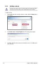
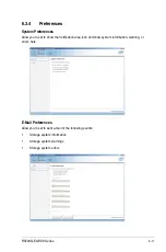
Page 130: ...Chapter 6 RAID Configuration 6 12 ...

Page 131: ... Driver Installation This chapter provides the instructions for installing the necessary drivers for different system components in both Linux and Windows Operating Systems Chapter 7 Driver Installation ...

Page 132: ...DVD to the USB flash drive To copy the RAID driver to a USB flash drive in Windows environment 1 Place the motherboard support DVD in the optical drive 2 Connect a USB flash drive to your system 3 Click on the optical drive to browse the contents of the support DVD 4 Click Drivers C620 INTEL RAID Windows Driver and then copy the RAID driver folder to the USB flash drive 7 1 2 Installing the RAID c...

Page 133: ...ver If you have only one optical drive installed in your system eject the Windows OS installation disc and replace with the motherboard Support DVD into the optical drive Click Browse to continue 5 Locate the driver in the corresponding folder of the Support DVD then click OK to continue 6 Select the RAID controller driver you need from the list and click Next ...

Page 134: ...em finishes loading the RAID driver replace the motherboard Support DVD with the Windows Server installation disc Select the drive to install Windows and click Next 8 Setup then proceeds with the OS installation Follow screen instructions to continue ...

Page 135: ...le ASSETUP EXE from the BIN folder Double click the ASSETUP EXE to run the support DVD The contents of the support DVD are subject to change at any time without notice Visit the ASUS website www asus com for the latest updates on software and utilities The support DVD that is bundled with your motherboard contains drivers management applications and utilities that you can install to maximize the f...

Page 136: ...vailable device drivers if the system detects installed devices Install the necessary drivers to activate the devices 7 3 2 Utilities menu tab The Utilities menu displays the software applications and utilities that the motherboard supports 7 3 1 Drivers menu tab ...

Page 137: ...ementary user guides You need an internet browser installed in your OS to view the User Guide 7 3 4 Contact information menu The Contact menu displays the ASUS contact information e mail addresses and useful links if you need more information or technical support for your motherboard ...

Page 138: ...ter and then log on with Administrator privileges 2 Insert the motherboard system support DVD into the optical drive The support DVD automatically displays the Drivers menu if Autorun is enabled in your computer If Autorun is NOT enabled in your computer browse the contents of the support DVD to locate the file ASSETUP EXE from the BIN folder Double click the ASSETUP EXE to run the support DVD 3 C...

Page 139: ...eries 7 9 5 Read the License Agreement and click Accept to continue the process 6 Read the Readme File Information and click Install to start the installation process 7 Click Restart Now to complete the setup process ...

Page 140: ...tel I350 AM2 I210 Gigabit Adapters Driver on the Windows operating system 1 Restart the computer 2 Log on with Administrator privileges 3 Insert the motherboard system support DVD to the optical drive If Autorun is NOT enabled in your computer browse the contents of the support DVD to locate the file ASSETUP EXE from the BIN folder Double click the ASSETUP EXE to run the support DVD 4 Click Intel ...

Page 141: ...ons Install Wizard window appears 7 Tick I accept the terms in the license agreement and click Next to continue 8 From the Setup Options window click Next to start the installation By default Intel R PROSet for Windows Device Manager and Windows PowerShell Module are ticked ...

Page 142: ...7 12 Chapter 7 Driver Installation 9 Click Install to start the installation 10 When the installation is done press Finish to complete the installation ...

Page 143: ... with Administrator privileges 2 Insert the motherboard system support DVD into the optical drive The support DVD automatically displays the Drivers menu if Autorun is enabled in your computer If Autorun is NOT enabled in your computer browse the contents of the support DVD to locate the file ASSETUP EXE from the BIN folder Double click the ASSETUP EXE to run the support DVD 3 Click the ASPEED AST...

Page 144: ...7 14 Chapter 7 Driver Installation 6 Click Finish to complete the installation 5 Click Install to start the installation process ...

Page 145: ...ogy enterprise 5 0 utility on a Windows operating system To install the Intel Rapid Storage Technology enterprise 5 0 utility 1 Restart the computer and then log on with Administrator privileges 2 Insert the motherboard system support DVD into the optical drive and navigate to the Utilities menu 3 Click the Intel Rapid Storage Technology enterprise to begin installation 4 The Intel Rapid Storage T...

Page 146: ...pter 7 Driver Installation 5 Read the Warning message and click Next to continue 6 Read the License Agreement and click Accept to continue the process 7 Select the destination folder and click Next to continue ...

Page 147: ...S720Q E9 RS8 Series 7 17 8 Tick the features that you would like to install and click Next to continue 9 Click Install to start the installation process 10 Click Restart Now to complete the setup process ...

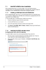
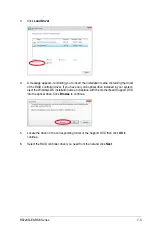
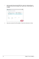
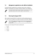
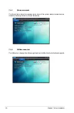
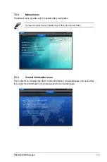
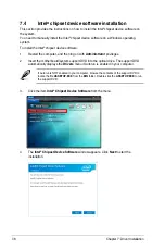
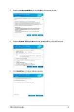
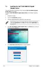
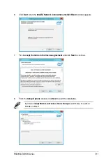
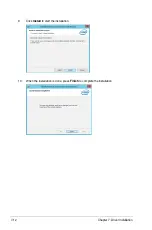
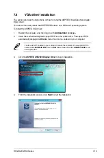
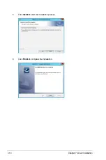
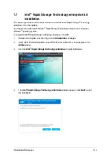
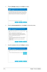
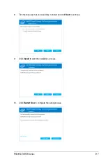
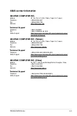
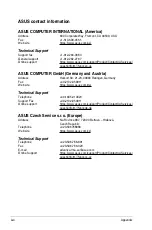
Page 148: ...7 18 Chapter 7 Driver Installation ...

Page 149: ...Appendix Appendix ...

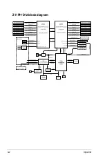
Page 150: ...A 2 Appendix Z11PH D12 block diagram ...

Page 151: ...dress 4F No 150 Li Te Rd Peitou Taipei 112 Taiwan Telephone 886 2 2894 3447 Fax 886 2 2890 7798 Web site https www asus com tw Technical Support Telephone 886 2 2894 3447 0800 093 456 Online Support https www asus com support Product ContactUs Services questionform lang zh tw ASUSTeK COMPUTER INC China Address No 5077 Jindu Road Minhang District Shanghai China Telephone 86 21 5442 1616 Fax 86 21 5...

Page 152: ...Harkort Str 21 23 40880 Ratingen Germany Fax 49 2102 959911 Web site https www asus com de Technical Support Telephone 49 1805 010923 Support Fax 49 2102 959911 Online support https www asus com support Product ContactUs Services questionform lang de de ASUS Czech Service s r o Europe Address Na Rovince 887 720 00 Ostrava Hrabová Czech Republic Telephone 420 596766888 Web site https www asus com c...

Page 153: ...ionform lang nl nl ASUS Polska Sp z o o Poland Address Ul Postępu 6 02 676 Warszawa Poland Web site https www asus com pl Technical Support Telephone 48 225718033 Online Support https www asus com support Product ContactUs Services questionform lang pl pl ASK Service Russia and CIS Address г Москва ул Орджоникидзе д 10 Россия Telephone 495 640 32 75 Web site https www asus com ru Technical Support...

Page 154: ...A 6 Appendix ...

Reviews: