Chapter 4: Motherboard Information
4-4
4.1.1
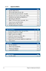
Layout contents
Jumpers
Page
1.
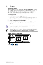
Clear RTC RAM (CLRTC1)
4-5
2.
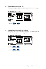
VGA controller setting (3-pin VGA_SW1)
4-6
3.
LAN controller setting (3-pin LAN_SW1, LAN_SW2)
4-6
4.
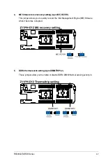
ME firmware force recovery setting (3-pin ME_RCVR1)
4-7
5.
DDR4 thermal event setting (3-pin DIMMTRIP1-2)
4-7
6.
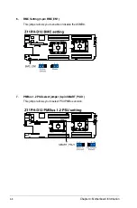
BMC Setting (3-pin BMC_EN1)
4-8
7.
PMBus 1.2 PSU select jumper (3-pin SMART_PSU1)
4-8
8.
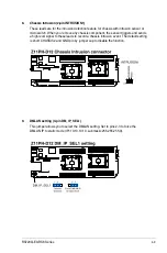
Chassis Intrusion (2-pin INTRUSION1)
4-9
9.
DMLAN setting (3-pin DM_IP_SEL1)
4-9
10.
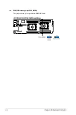
PCH_MFG setting (3-pin PCH_MFG1)
4-10
Internal connectors
Page
1.
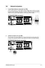
Trusted Platform Module connector (20-1 pin TPM1)
4-11
2.
Serial port connector (10-1 pin COM1)
4-11
3.
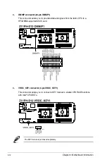
OMNIP connector (24-pin OMNIP1)
4-12
4.
VROC_KEY connector (4-pin VROC_KEY1)
4-12
5.
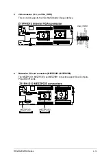
VGA connector (16-1 pin VGA_HDR1)
4-13
6.
Mezzanine PCI card connectors (MEZZPCIE1; MEZZPCIE2)
4-13
7.
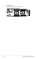
Power connector
4-14
Internal LEDs
Page
1.
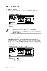
BMC LED (BMCLED1)
4-15
2.
Standby Power LED (SBPWR1)
4-15
3.
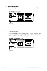
Message LED (MESLED1)
4-16
4.
Location LED (LOCLED1)
4-16
Mid Plane jumper
Page
1.
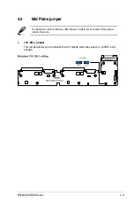
12V_SEL1 jumper
4-17
Summary of Contents for RS720Q-E9-RS8
Page 1: ...2U Rackmount Server RS720Q E9 RS8 User Guide ...
Page 12: ...xii ...
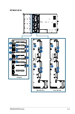
Page 45: ...2 21 RS720Q E9 RS8 Series RS720Q E9 RS8 Upper Mid Plane Lower Mid Plane Backplane ...
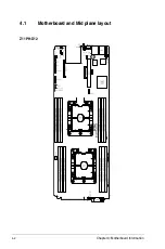
Page 56: ...Chapter 4 Motherboard Information 4 2 4 1 Motherboard and Mid plane layout Z11PH D12 ...
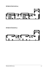
Page 57: ...4 3 RS720Q E9 RS8 Series RS720Q E9 RS8 S Mid Plane RS720Q E9 RS8 Mid Plane ...
Page 72: ...Chapter 4 Motherboard Information 4 18 ...
Page 118: ...Chapter 5 BIOS Setup 5 46 ...
Page 130: ...Chapter 6 RAID Configuration 6 12 ...
Page 148: ...7 18 Chapter 7 Driver Installation ...
Page 149: ...Appendix Appendix ...
Page 150: ...A 2 Appendix Z11PH D12 block diagram ...
Page 154: ...A 6 Appendix ...

