ASUS TS100-E10-PI4
3-17
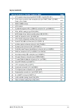
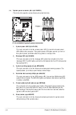
13. System Management Bus (SMBUS) connector (5-1 pin SMBUS1)
This connector controls the system and power management-related tasks. This
connector processes the messages to and from devices rather than tripping the
individual control lines.
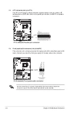
14. Chassis intrusion connector (2-pin INTRUSION1)
This connector is for a chassis-mounted intrusion detection sensor or switch. Connect
one end of the chassis intrusion sensor or switch cable to this connector. The chassis
intrusion sensor or switch sends a high-level signal to this connector when a chassis
component is removed or replaced. The signal is then generated as a chassis intrusion
event.
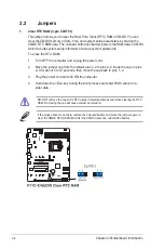
By default, the pin labeled “Chassis Signal” and “Ground” are shorted with a jumper
cap. Remove the jumper caps only when you intend to use the chassis intrusion
detection feature.
Summary of Contents for TS100-E10-PI4
Page 1: ...Pedestal Server TS100 E10 PI4 User Guide ...
Page 10: ...x ...
Page 42: ...Chapter 3 Motherboard Information 3 2 3 1 Motherboard layout ...
Page 60: ...Chapter 3 Motherboard Information 3 20 ...
Page 118: ...5 18 Chapter 5 RAID Configuration ...
Page 125: ...ASUS TS100 E10 PI4 6 7 5 Follow the onscreen instructions to complete the installation ...
Page 126: ...6 8 Chapter 6 Driver Installation ...
Page 128: ...A 2 Appendix P11C X AUDIO block diagram ...
Page 138: ...A 12 Appendix ...

