


ASUS TS700-E8-PS4 V2, TS700-E8-RS8 V2
4-3
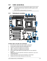
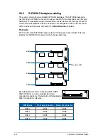
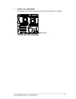
Jumpers
Page
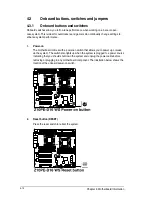
1. Clear RTC RAM (CLRTC1)
4-14
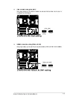
2. VGA controller setting (VGA_SW1)
4-15
3. SMBUS connection setting (TESLA_M_SW)
4-15
4. RAID selection jumper setting (3-pin RAID_SEL1)
4-16
5. ME firmware force recovery setting (3-pin ME_RCVR1)
4-16
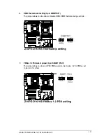
6. DDR4 thermal event setting (3-pin DIMMTRIP1)
4-17
7. PMBus 1.2 PSU select jumper (3-pin SMART_PSU1)
4-17
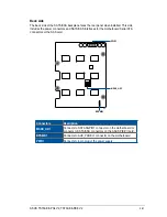
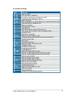
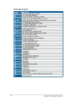
Internal connectors
Page
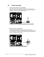
1. Hard disk activity LED connector (4-pin HDLED1)
4-18
2. USB 2.0 connectors (10-1 pin USB1112)
4-18
3. USB 3.0 connector (20-1 pin USB3_56)
4-19
4. CPU, front and rear fan connectors (4-pin CPU_FAN1-2,
FRNT_FAN1–5, REAR_FAN1-2)
4-19
5. Power supply SMBus Connector (PSUSMB1)
4-20
6. Serial port connectors (10-1 pin COM1)
4-20
7. Serial ATA 6.0/3.0 Gb/s connectors (7-pin SATA_1-6 [gray])
Serial ATA 6.0/3.0 Gb/s connectors (7-pin SSATA_1-4 [gray])
4-21
8. Serial General Purpose Input/Output connector (6-1 pin SGPIO1,
SSGPIO1)
4-22
9. M.2 (NGFF) connector (NGFF1)
4-22
10. Trusted Platform Module connector (20-1 pin TPM1)
4-23
11. EATX power connectors (24-pin EATXPWR1; 8-pin EATX12V1/
EATX12V2; 6-pin EATX12V3)
4-23
12. Chassis Intrusion (2-pin INTRUSION1)
4-24
13. System panel connector (20-1 pin PANEL1)
4-25
14. Auxiliary panel connector (20-2 pin AUX_PANEL1)
4-26
15. Digital audio connector (4-1 pin SPDIF_OUT)
4-27
16. VGA connector (VGA_HDR1)
4-27
17. Front panel audio connector (10-1 pin AAFP)
4-28
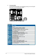
Onboard buttons and switches
Page
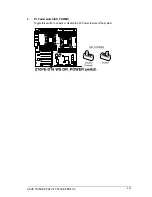
1. Power-on button
4-12
2. Reset button
4-12
3. Dr. Power switch (DR_POWER)
4-13
Summary of Contents for TS700-E8-PS4 V2
Page 1: ...Server User Guide TS700 E8 PS4 V2 TS700 E8 RS8 V2 ...
Page 24: ...Chapter 1 Product Introduction 1 12 ...
Page 60: ...Chapter 2 Hardware Setup 2 36 ...
Page 150: ...5 58 Chapter 5 BIOS Setup ...
Page 188: ...6 38 Chapter 6 RAID Configuration ...
Page 210: ...A 2 Appendix Z10PE D16 WS block diagram ...
Page 214: ......