


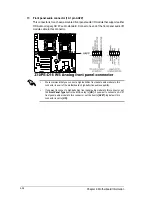


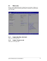


Chapter 4: Motherboard Information
4-26
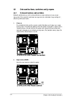
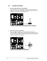
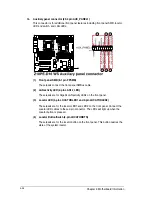
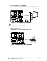
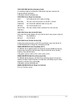
14. Auxiliary panel connector (20-2 pin AUX_PANEL1)
This connector is for additional front panel features including front panel SMB, locator
LED and switch, and LAN LEDs.
(1) Front panel SMB (6-1 pin FPSMB)
These leads connect the front panel SMBus cable.
(2) LAN activity LED (2-pin LAN12_LED)
These leads are for Gigabit LAN activity LEDs on the front panel.
(3) Locator LED (2-pin LOCATORLED1 and 2-pin LOCATORLED2)
These leads are for the locator LED1 and LED2 on the front panel. Connect the
Locator LED cables to these 2-pin connector. The LEDs will light up when the
Locator button is pressed.
(4) Locator Button/Swich (2-pin LOCATORBTN)
These leads are for the locator button on the front panel. This button queries the
state of the system locator.
Summary of Contents for TS700-E8-PS4 V2
Page 1: ...Server User Guide TS700 E8 PS4 V2 TS700 E8 RS8 V2 ...
Page 24: ...Chapter 1 Product Introduction 1 12 ...
Page 60: ...Chapter 2 Hardware Setup 2 36 ...
Page 150: ...5 58 Chapter 5 BIOS Setup ...
Page 188: ...6 38 Chapter 6 RAID Configuration ...
Page 210: ...A 2 Appendix Z10PE D16 WS block diagram ...
Page 214: ......


