background image

Service Manual

7

Installation tools

Screwdriver

Plastic blade

Tweezers

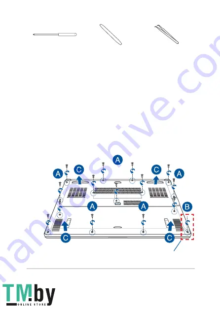
Removing the compartment cover

A. 

Remove the screw(s) from the Notebook PC’s compartment cover.

B. 

Loosen the Pop-open Screw without removing the screw from 

the cover.

C. 

Pull out the compartment cover and remove it completely from 

your Notebook PC.

Pop-open Screw

 
https://tm.by 

Интернет

-

магазин

 TM.by

Summary of Contents for TUF DASH FX516PM

Page 1: ...More info E17960 First Edition January 2021 SERVICE MANUAL https tm by Интернет магазин TM by ...

Page 2: ...STRUED AS A COMMITMENT BY ASUS ASUS ASSUMES NO RESPONSIBILITY OR LIABILITY FOR ANY ERRORS OR INACCURACIES THAT MAY APPEAR IN THIS MANUAL INCLUDING THE PRODUCTS AND SOFTWARE DESCRIBED IN IT Copyright 2021 ASUSTeK COMPUTER INC All Rights Reserved LIMITATION OF LIABILITY Circumstances may arise where because of a default on ASUS part or other liability you are entitled to recover damages from ASUS In...

Page 3: ...aimer 4 Safety precautions 4 Major components 6 Installation tools 7 Removing the compartment cover 7 Cover screw map 9 Installing a RAM module 10 Installing an M 2 card 12 Wiring and connection diagrams 14 https tm by Интернет магазин TM by ...

Page 4: ...s Detach the clip or flap before removing the signal cables to prevent damage Disconnect the power plug by pulling the plug evenly to avoid damage Ensure to connect the signal cables in the correct orientation Disconnect all power cables and remove the battery pack if applicable before cleaning your Notebook PC with liquid detergent to avoid risk of electric shock Disconnect all power cables and r...

Page 5: ...the edges to avoid touching the ICs Ensure to properly install all the components before connecting the AC power Do not use power adapters or batteries from other devices to reduce the risk of injury to persons due to fire or explosion Use only certified power adapters or batteries supplied by the manufacturer or authorized retailers Ensure to install the correct screw models on your Notebook PC t...

Page 6: ...or Keyboard RAM module SSD module LCD panel module Power adapter Battery and power connector Major components Power supply connector HDMI connector USB Type A connector LAN connector Headphone jack USB Type A connector USB Type A connector https tm by Интернет магазин TM by ...

Page 7: ...he compartment cover A Remove the screw s from the Notebook PC s compartment cover B Loosen the Pop open Screw without removing the screw from the cover C Pull out the compartment cover and remove it completely from your Notebook PC Pop open Screw https tm by Интернет магазин TM by ...

Page 8: ...To reattach the compartment cover A Align and reattach the cover of the compartment B Secure the cover using the screw s you removed earlier C Tighten the Pop open Screw Pop open Screw https tm by Интернет магазин TM by ...

Page 9: ...Service Manual 9 Cover screw map M2 X 9 5 7PCS M2 X 8 7PCS M2 5 X 8 1PC Pop open Screw https tm by Интернет магазин TM by ...

Page 10: ...ack etc before removing the compartment cover IMPORTANT Visit an authorized service center or retailer for information on RAM module upgrades for your Notebook PC Purchase RAM modules from authorized retailers of this Notebook PC to ensure maximum compatibility and reliability NOTE The appearance of your Notebook PC s bottom view and RAM module may vary per model but the RAM module installation re...

Page 11: ...NOTE For more details refer to the Removing the compartment cover section in this manual B Align and insert the RAM module into the RAM module slot C Push down the RAM module until it clicks in place 30 angle notches https tm by Интернет магазин TM by ...

Page 12: ...y telephone or telecommunication lines and power connector such as external power supply battery pack etc before removing the compartment cover NOTE The appearance of your Notebook PC s bottom view and M 2 card may vary per model but the module installation remains the same It is recommended that you install the M 2 card under professional supervision You may also visit an authorized service cente...

Page 13: ...nt cover NOTE For more details refer to the Removing the compartment cover section in this manual B Align and insert the M 2 card into the module slot C Secure the M 2 card in place using the bundled screw s https tm by Интернет магазин TM by ...

Page 14: ...14 Service Manual Wiring and connection diagrams Top View https tm by Интернет магазин TM by ...

Page 15: ...nector 3 LAN connector 12 Touchpad connector 4 HDMI connector 13 Keyboard connector 5 USB Type A connector 14 WLAN connector 6 USB Type C connector 15 Fan connector 7 Headphone jack 16 DDR4 DIMM connector 8 Speaker connector 17 Power key connector 9 SSD connector Bottom View https tm by Интернет магазин TM by ...

Page 16: ...https tm by Интернет магазин TM by ...

Reviews: