


ASUS TX97-N User’s Manual
36
IV. BIOS SOFTWARE
IV
. BIOS
(Standard CMOS)
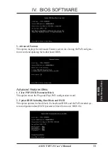
Load Defaults
Load BIOS Defaults loads the minimized settings for troubleshooting. Load Setup
Defaults, on the other hand, is for loading optimized defaults for regular use. Choosing
defaults at this level will modify all applicable settings.
A section at the bottom of the preceding screen displays the control keys for this
screen. Take note of these keys and their respective uses. Another section just below
the control keys section displays information on the currently highlighted item in the
list.
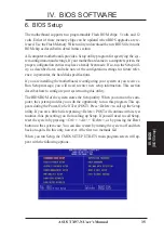
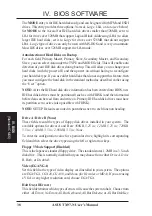
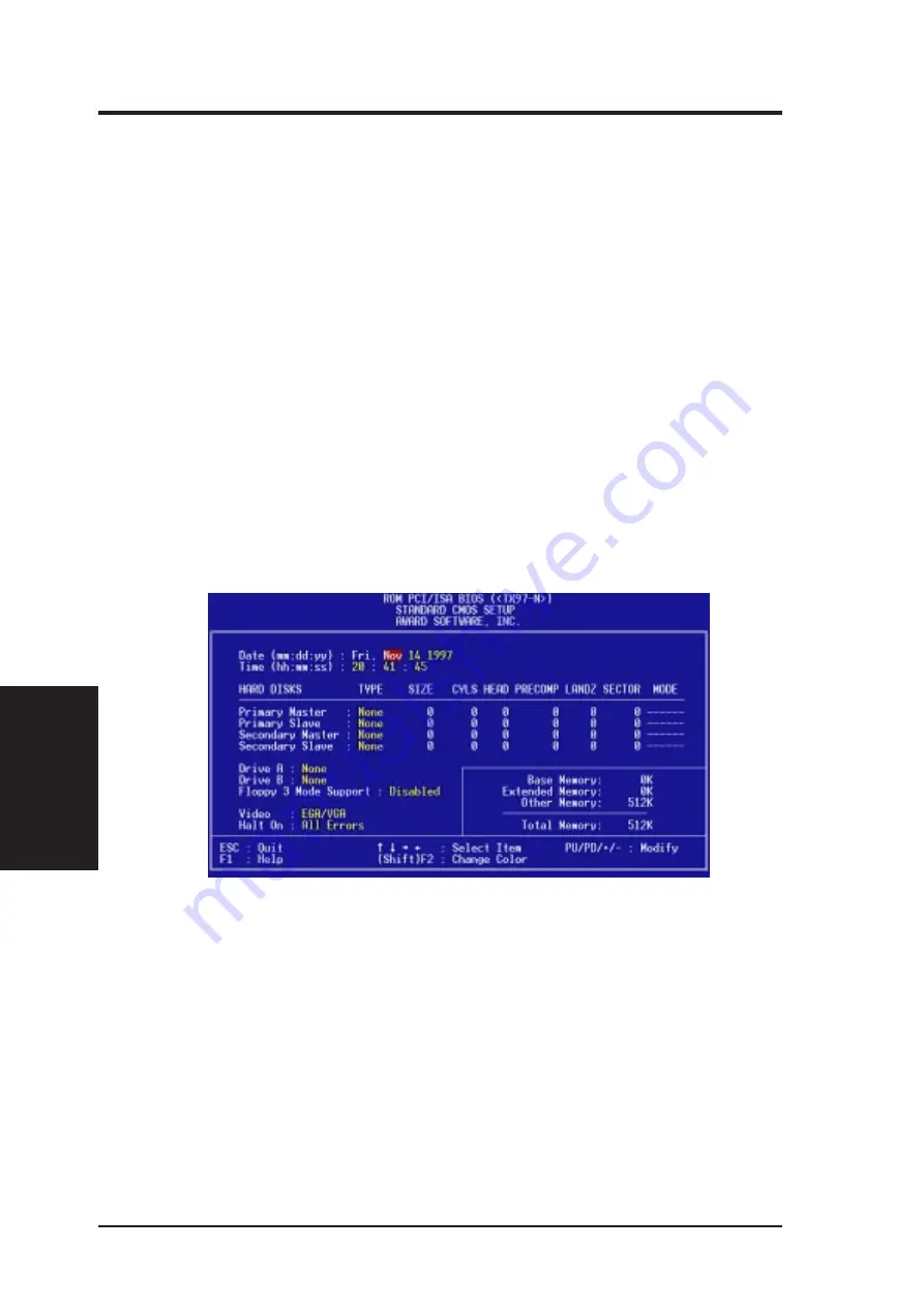
Standard CMOS Setup
Standard CMOS Setup allows you to record some basic system hardware configu-
ration and set the system clock and error handling. If the motherboard is already
installed in a working system, you will not need to select this option anymore. How-
ever, if the configuration stored in the CMOS memory on the board gets lost or
damaged, or if you change your system hardware configuration, you will need to
respecify the configuration values. The configuration values usually get lost or cor-
rupted when the power of the onboard CMOS battery weakens.
User-configurable fields appear in a different color. If you need information on the
selected field, press <F1>. The help menu will then appear to provide you with the
information you need. The memory display at the lower right-hand side of the screen
is read-only and automatically adjusts accordingly.


