background image

ASUS TXP4-X User’s Manual

61

Terminator Settings for the ASUS PCI-SC860

Many SCSI devices including the ASUS PCI-SC860 use a set of onboard active
resistors to terminate the devices at the ends automatically. Automatic termination
requires that the SCSI devices be connected in a straight linear connection or “chain.”
Connect SCSI devices to one or two of the SCSI connectors in a linear “chain” for
auto termination of the ASUS PCI-SC860 to be effective.  Other formations will
cause your SCSI devices to not mount properly.  You must use the end of the ribbon
cable when using the internal connector(s) to keep a linear path.

Additional Note:  The Symbios Logic SCSI Configuration Utility is a powerful
tool.  If, while using it, you somehow disable all your controllers or cannot enter
the configuration utility, pressing Ctrl-A after memory count during reboot
allows you to recover and reconfigure.

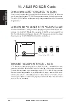
Terminator Settings for the ASUS PCI-SC200

The ASUS PCI-SC200, on the other hand, has “active” termination that you must
set using jumper JP5.  There are two settings, “terminated” and “not terminated,” as
shown below.

Terminator Setting (Terminated / Not Terminated)

JP
 5

Terminated (Default)

Not Terminated

JP
 5

Decide whether or not you need to terminate the ASUS PCI-SC200 based on its
position in the SCSI chain. Only the devices at each end of the chain need to be
terminated.  If you have only internal or only external devices connected to the
ASUS PCI-SC200, then you must terminate the ASUS PCI-SC200.  If you have
both internal and external devices connected, you must not terminate the card.  See
the following example which illustrates this concept.

VI. 

ASUS SCSI Cards

(Jumpers)

VI.  ASUS PCI SCSI Cards

Summary of Contents for TXP4-X

Page 1: ...R TXP4 X Pentium ATX Motherboard USER S MANUAL ...

Page 2: ...only for identification or explanation and to the owners benefit without intent to infringe Intel LANDesk and Pentium are registered trademarks of Intel Corporation IBM and OS 2 are registered trademarks of International Business Machines Symbios is a registered trademark of Symbios Logic Corporation Windows and MS DOS are registered trademarks of Microsoft Corporation Sound Blaster AWE32 and SB16...

Page 3: ...sus com tw FTP ftp asus com tw pub ASUS ASUS COMPUTER INTERNATIONAL Marketing Info Address 721 Charcot Avenue San Jose CA 95131 USA Telephone 1 408 474 0567 Fax 1 408 474 0568 Email info usa asus com tw Technical Support BBS 1 408 474 0569 Email tsd usa asus com tw WWW www asus com ASUS COMPUTER GmbH Marketing Info Address Harkort Str 25 40880 Ratingen BRD Germany Telephone 49 2102 445011 Fax 49 2...

Page 4: ...r Settings 15 Compatible Cyrix CPU Identification 16 2 System Memory SIMM DIMM 18 SIMM Memory Installation 20 DIMM Memory Installation Procedures 21 3 Central Processing Unit CPU 22 4 Expansion Cards 23 Expansion Card Installation Procedure 23 Assigning IRQs for Expansion Cards 23 Assigning DMA Channels for ISA Cards 24 5 External Connectors 25 Power Connection Procedures 33 IV BIOS SOFTWARE 34 Su...

Page 5: ... and User Password 53 IDE HDD Auto Detection 54 Save Exit Setup 55 Exit Without Saving 55 Desktop Management Interface DMI 56 Introducing the ASUS DMI Configuration Utility 56 System Requirements 56 Using the ASUS DMI Configuration Utility 57 VI ASUS PCI SCSI Cards 59 Symbios SCSI BIOS and Drivers 59 ASUS PCI SC200 PCI SC860 SCSI Cards 59 Setting Up the ASUS PCI SC200 PCI SC860 60 Setting the INT ...

Page 6: ...lar installation If this equipment does cause harmful interference to radio or television reception which can be determined by turning the equipment off and on the user is encouraged to try to correct the inter ference by one or more of the following measures Re orient or relocate the receiving antenna Increase the separation between the equipment and receiver Connect the equipment to an outlet on...

Page 7: ...Installation of ASUS SCSI cards optional Item Checklist Please check that your package is complete If you discover damaged or missing items please contact your retailer þ The ASUS TXP4 X motherboard þ 1 IDE ribbon cable þ 1 floppy ribbon cable þ Support Drivers Utilities Flash Memory Writer utility to update the FLASH BIOS Desktop Management Interface DMI utility TX patch files for Windows 95 Read...

Page 8: ...t PCI slots Super Multi I O Provides two high speed UART compatible serial ports and one parallel port with EPP and ECP capabilities Desktop Management Interface DMI Supports DMI through BIOS which allows hardware to communicate within a standard protocol creating a higher level of compatibility Requires DMI enabled components See section V PCI Bus Master IDE Controller Comes with an onboard PCI B...

Page 9: ... transfers from PCI master busses to memory to CPU ACPI Ready ACPI Advanced Configuration and Power Interface is also implemented on all ASUS 430TX series of motherboards ACPI provide more Energy Saving Features for the future operating systems OS supporting OS Direct Power Management OSPM functionality With these features imple mented in the OS PCs can be ready around the clock yet satisfy all th...

Page 10: ...10 ASUS TXP4 X User s Manual This page is intentionally left blank ...

Page 11: ... Parts Intel s 430TX PCIset 512KB Pipelined Burst L2 Cache CPU ZIF Socket 7 3 PCI Slots 3 ISA Slots 2 DIMM Sockets T USB Port 1 B USB Port 2 Programmable Flash ROM T PS 2 Mouse B PS 2 Keyboard T Parallel Conn B Serial Conn COM 1 COM 2 4 SIMM Sockets II FEATURES ISA PCI Shared Slot ...

Page 12: ... IrDA IDE LED FANPWR3 SIMM Socket 1 32 bit 72 pin module SIMM Socket 2 32 bit 72 pin module SIMM Socket 3 32 bit 72 pin module SIMM Socket 4 32 bit 72 pin module 3 2 3 2 1 0 1 0 Row PS 2 T Mouse B Keyboard T USB 1 B USB 2 USB DIMM Socket 2 64 bit 168 pin module DIMM Socket 1 64 bit 168 pin module 3 2 1 0 Row VID0 VID1 VID2 CPU Voltage VID3 CPU Fan BF0 BF1 BF2 BUS Freq Board Power Input for ATX Pow...

Page 13: ... 2 Mouse Connector 6 pin female 3 PRINTER p 26 Parallel Printer Port Connector 25 pin female 4 COM1 COM2 p 26 Serial Port COM1 COM2 two 9 pin female 5 FLOPPY p 26 Floppy Drive Connector 34 pin block 6 USB p 27 Universal Serial BUS Ports 1 2 two 4 pin female 7 Primary Second IDE p 27 Primary Secondary IDE Connector 40 pin blocks 8 IDELED p 28 IDE LED Activity Light 2 pins 9 FANPWR1 2 3 p 28 Chassis...

Page 14: ... connect pins 2 3 Jumpers with two pins will be shown as for Short On and for Open Off For manufacturing simplicity the jump ers may be sharing pins from other groups Use the diagrams in this manual instead of following the pin layout on the board Settings with two jumper numbers require that both jumpers be moved together To connect the pins simply place a plastic jumper cap over the two pins as ...

Page 15: ...Turn off your computer and remove theAC power 2 Move this jumper to Clear Data 3 Move the jumper back to Operation 4 Turn on your computer 5 Hold down Delete during bootup and enter BIOS setup to reenter user preferences Battery Test Jumper RTCLR You can test the battery s current by removing this jumper and attaching a cur rent meter to pins 1 2 WARNING You must unplug the power cord to your powe...

Page 16: ... 200MHz Pentium MMX P55C 150MHz 233MHz AMD K6 PR166 and faster AMD K5 PR75 PR133 IBM Cyrix 6x86 MX PR166 and faster IBM Cyrix 6x86 M1 PR166 and faster Manufacturer CPU Type Single Plane Dual Plane VID3 VID2 VID1 VID0 Intel AMD IBM Cyrix P54C CS K5 M1 3 5V VRE 2 3 2 3 1 2 AMD K6 PR166 200 2 9 Volts Intel AMD P54C CS K5 3 4V STD 2 3 2 3 2 3 Intel IBM Cyrix P55C 6x86MX 2 8 Volts AMD K6 PR233 3 2 Volt...

Page 17: ...ollows BUS Freq Freq Ratio CPU Model Freq Ratio BUS Freq FS2 FS1 FS0 BF1 BF0 Intel Pentium 233MHz 3 5x 66MHz 2 3 1 2 2 3 1 2 1 2 Intel Pentium 200MHz 3 0x 66MHz 2 3 1 2 2 3 2 3 1 2 Intel Pentium 166MHz 2 5x 66MHz 2 3 1 2 2 3 2 3 2 3 Intel Pentium 150MHz 2 5x 60MHz 2 3 2 3 1 2 2 3 2 3 Intel Pentium 133MHz 2 0x 66MHz 2 3 1 2 2 3 1 2 2 3 Intel Pentium 120MHz 2 0x 60MHz 2 3 2 3 1 2 1 2 2 3 Intel Penti...

Page 18: ...18 ASUS TXP4 X User s Manual This page was left intentionally blank ...

Page 19: ... on the motherboard IMPORTANT Memory speed setup is required through Auto Configuration in BIOS Chipset Setup of the BIOS SOFTWARE If both 60ns and 70ns memory are used set Auto Configuration to 70ns Do not use memory modules with more than 24 chips per module Modules with more than 24 chips exceed the design specifica tions of the memory subsystem and will be unstable Memory Socket SIMM Memory Mo...

Page 20: ...ng from a 45 degree angle making sure that all the contacts are aligned with the socket 3 With your finger tips rock the memory module into a vertical position so that it clicks into place 72 Pin DRAM in SIMM Socket Support Clip Safety Tab This Side Only Mounting Hole 4 The plastic guides should go through the two mounting holes on the sides and the support clips should snap on the other side 5 To...

Page 21: ...ts 88 Pins 60 Pins 20 Pins Lock R The Dual Inline Memory Module DIMM memory modules must be 3 3Volt Un buffered Synchronous DRAM SDRAM or Extended Data Output EDO You can identify the type of DIMM module by the illustration below 168 Pin DIMM Notch Key Definitions 3 3V DRAM Key Position Voltage Key Position Unbuffered RFU Buffered Reserved 3 3V 5 0V The notch on the DIMM module will shift between ...

Page 22: ...pwards to a 90 degree right angle Insert the CPU with the correct orientation as shown Use the notched corner of the CPU as your guide The white dot should point towards the end the of the lever Notice that there is a blank area where one hole is missing from that corner of the square array of pin holes and a 1 printed on the motherboard next to that corner Because the CPU has a corner pin for thr...

Page 23: ...n there are 16 IRQs available but most of them are already in use leaving 6 IRQs free for expansion cards Both ISA and PCI expansion cards may require to use IRQs System IRQs are avail able to cards installed in the ISA expansion bus first then any remaining IRQs are available to PCI cards Currently there are two types of ISAcards The original ISA expansion card design now referred to as legacy IS...

Page 24: ... legacy and PnP ISA cards In the PCI bus design the BIOS automatically assigns an IRQ to a PCI slot that contains a card requiring an IRQ Leave all PCI INT assignments on A PCI slot 1 automatically assigns an INT letter starting fromA B C D PCI slot 2 assigns B C D A slot 3 assigns C D A B and slot 4 assigns D A B C in these orders therefore manual offsetting is not necessary Assigning DMA Channel...

Page 25: ...1 PS 2 Keyboard Connector 6 pin Female This connection is for a standard keyboard using an PS 2 plug mini DIN This connector will not allow standard AT size large DIN keyboard plugs You may use a DIN to mini DIN adapter on standard AT keyboards PS 2 Keyboard 6 pin Female 2 PS 2 Mouse Connector 6 pin Female The system will direct IRQ12 to the PS 2 mouse if one is detected If not de tected expansion...

Page 26: ...wo serial ports can be used for pointing devices or other serial devices See Onboard Serial Port in Chipset Features Setup of the BIOS SOFTWARE COM 1 COM 2 Serial Ports 9 pin Male 5 Floppy Disk Drive Connector 34 1pin FLOPPY This connector supports the provided floppy disk drive ribbon cable After con necting the single end to the board connect the two plugs on the other end to the floppy drives P...

Page 27: ...dingly Please refer to the docu mentation of your hard disk for the jumper settings BIOS now supports SCSI device or IDE CD ROM bootup see HDD Sequence SCSI IDE First Boot Sequence in the BIOS Features Setup of the BIOS SOFTWARE Pin 20 is removed to prevent inserting in the wrong orientation when using ribbon cables with pin 20 plugged TIP You may configure two hard disks to be both Masters using ...

Page 28: ...s instead of the expansion slots Depending on the fan manufacturer the wiring and plug may be different The red wire should be positive while the black should be ground Connect the fan s plug to the board taking into consid eration the polarity of the this connector NOTE The Rotation signal is to be used only by a specially designed fan with rotation signal WARNING The CPU and or motherboard will ...

Page 29: ... Infrared Module Connector IRRX 5V IRTX FIRRX GND For the infrared feature to be available you must connect the optional Infrared IrDA module to the motherboard R 11 ATX Power Supply Connector 20 pin ATXPWR This connector connects to a ATX power supply The plug from the power sup ply will only insert in one orientation because of the different hole sizes Find the proper orientation and push down f...

Page 30: ... If you want to use this connector Suspend Switch in the Power Management Setup of the BIOS SOFTWARE section should be on the default setting of Enable 14 ATX Power Switch Soft Power Switch PWR SW The system power is controlled by a momentary switch connected to this lead Pushing the button once will switch the system between ON and SLEEP Push ing the switch while in the ON mode for more than 4 se...

Page 31: ...ASUS TXP4 X User s Manual 31 This page was left intentionally blank ...

Page 32: ...32 ASUS TXP4 X User s Manual This page was left intentionally blank ...

Page 33: ...onitor LED may light up after the system s if it complies with green stan dards or if it has a power standby feature The system will then run power on tests While the tests are running additional messages will appear on the screen If you do not see anything within 30 seconds from the time you turn on the power the system may have failed a power on test Recheck your jumper set tings and connections...

Page 34: ... BIOS to File Flash Memory Writer Utility The flash memory writer utility must be run while the system is in real mode In particular the Update BIOS Main Block From File and Update BIOS Including Boot Block and ESCD options require real mode To run this utility boot from a system floppy disk without the AUTOEXEC BAT and CONFIG SYS files IMPORTANT If unknown is displayed after Flash Type the memory...

Page 35: ... from the current boot block this option will not update the main block Instead it will display the following messages Boot Block of New BIOS is different from old one Please Use Advanced Features to flash whole BIOS 3 Advanced Features This option displays the Advanced Features screen for clearing the PnP configura tion record and updating the motherboard BIOS Advanced Features Menu 1 Clear PNP E...

Page 36: ...the A prompt type PFLASH and then press Enter 5 Enter 2 Update BIOS Main Block From File from the Main Menu or option 2 Update BIOS Including Boot Block and ESCD from the Advanced Features Menu if prompted by option 2 of the Main Menu 6 The program displays a second screen prompting you for the name of the BIOS file Type in the complete file name and extension of the new BIOS and then press Enter ...

Page 37: ...u are installing the motherboard reconfiguring your system or you receive a Run Setup message you will need to enter new setup information This section describes how to configure your system using this utility The BIOS ROM of the system stores the Setup utility When you turn on the com puter the system provides you with the opportunity to run this program This ap pears during the Power On Self Tes...

Page 38: ...ration stored in the CMOS memory on the board gets lost or damaged or if you change your system hardware configuration you will need to respecify the configuration values The configuration values usually get lost or cor rupted when the power of the onboard CMOS battery weakens The preceding screen provides you with a list of options At the bottom of this screen are the control keys Take note of th...

Page 39: ...rboard see section VI for instructions If you install other vendor s SCSI controller card refer to their respective documentations on how to install the required SCSI drivers For IDE hard disk drive setup you can Use the Auto setting for detection during bootup Use the IDE HDD AUTO DETECTION in the main menu to automatically enter the drive specifications Enter the specifications yourself manually...

Page 40: ...ble with FDISK NOTE SETUP Defaults are noted in parenthesis next to each function heading Drive A Drive B None These fields record the types of floppy disk drives installed in your system The available options for drives A and B are 360KB 5 25 in 1 2MB 5 25 in 720KB 3 5 in 1 44MB 3 5 in 2 88MB 3 5 in None To enter the configuration value for a particular drive highlight its corresponding field and...

Page 41: ...ion heading Details of BIOS Features Setup Virus Warning Disabled This field protects the boot sector and partition table of your hard disk against accidental modifications Any attempt to write to them will cause the system to halt and display a warning message If this occurs you can either allow the operation to continue or use a bootable virus free floppy disk to reboot and investigate your syst...

Page 42: ...lti sector transfers instead of one sector per transfer Most IDE drives except older versions can utilize this feature Selections are HDD MAX Disabled 2 4 8 16 and 32 Security Option System This field determines when the system prompts for the password The default set ting is System where the system prompts for the User Password every time you boot up The other option is Setup where the system alw...

Page 43: ...d 1024KB by the amount used for this purpose Boot Up NumLock Status On This field enables users to activate the Number Lock function upon system boot Boot Up System Speed High This has no function and should be left on the setup default Typematic Rate Setting Disabled When enabled you can set the two typematic controls listed next Setup default setting is Disabled Typematic Rate Chars Sec 6 This f...

Page 44: ...ult or check with your vendor for DIMM specs SDRAM Speculative Read Disabled If Enabled the CPU will issue predict commands to access the DRAM if a miss occurs the CPU will cancel this command Some operating systems under certain situations have a problem utilizing this feature so it is normally Disabled Passive Release Enabled This is a mechanism that allows concurrency of ISA EISA cycles and CPU...

Page 45: ...er assignments set this field to Swap AB and the swap will be controlled by the onboard chipset Onboard Serial Port 1 3F8H IRQ4 Settings are 3F8H IRQ4 2F8H IRQ3 3E8H IRQ4 2E8H IRQ10 and Disabled for the onboard serial connector Onboard Serial Port 2 2F8H IRQ3 Settings are 3F8H IRQ4 2F8H IRQ3 3E8H IRQ4 2E8H IRQ10 and Disabled for the onboard serial connector Onboard Parallel Port 378H IRQ7 This fie...

Page 46: ...the Primary IDE channel Secondary IDE channel Both or Disable both channels for systems with only SCSI drives IDE Ultra DMA Mode Auto This sets the IDE UltraDMA to be active when using UltraDMA capable IDE de vices The BIOS will automatically adjust or disable this setting for slower IDE devices so that Auto or high settings will not cause problems for older IDE devices Choose Disable if you do no...

Page 47: ...features Min Saving puts the system into power saving mode after 40 min of system inactivity Max Saving puts the system into power saving mode after 30 sec of system inactivity IMPORTANT Advanced Power Management APM should be installed to keep the system time updated when the computer enters suspend mode acti vated by the BIOS Power Management For DOS environments you need to add DEVICE C DOS POW...

Page 48: ...ected from the enabled IRQ channels HDD Power Down Disable shuts down any IDE hard disk drives in the system after a period of inactivity This time period is user configurable to 1 15 Mins or Disable This feature does not af fect SCSI hard disks Doze Mode Standby Mode Suspend Mode Disable These fields set the period of time after which each of these modes activate 30 Sec 1 Min 2 Min 4 Min 8 Min 20...

Page 49: ... modem off and then back on while the computer is off causes an initializa tion string that will also cause the system to power on AC PWR Loss Restart Disabled Allows you to set whether you want your system to boot up after the power has been interrupted Disabled leaves your system off after reapplying power and Enabled boots up your system after replying power Automatic Power Up Disabled Allows y...

Page 50: ...IRQ use is determined for each PCI slot The default setting for each field is Auto which uses auto routing to determine IRQ use The other options are manual settings of NA 5 7 9 10 11 12 14 or 15 for each slot PCI Latency Timer 32 PCI Clock The default setting of 32 PCI Clock enables maximum PCI performance for this motherboard IRQ xx Used By ISA No ICU These fields indicate whether or not the dis...

Page 51: ...M Block BASE No ICU This field allows you to set the base address and block size of a legacy ISA card that uses any memory segment within the C800H and DFFFH address range If you have such a card and you are not using an ICU to specify its address range select a base address from the six available options the ISA MEM Block SIZE field will then appear for selecting the block size If you have more t...

Page 52: ...een Press Y and then Enter to con firm Press N and then Enter to abort This feature does not affect the fields on the Standard CMOS Setup screen Load Setup Defaults This Load Setup Defaults option allows you to load the default values to the sys tem configuration fields These default values are the optimized configuration set tings for the system To load these default values highlight Load Setup D...

Page 53: ...te that the password is case sensitive and can be up to 8 alphanumeric characters long type your password and then press Enter The system confirms your password by ask ing you to type it again After setting a password the screen automatically reverts to the main screen To implement password protection specify in the Security Option field of the BIOS Features Setup screen when the system will promp...

Page 54: ...e En hanced IDE support for four devices you can only install two IDE hard disk drives Your IDE controller must support the Enhanced IDE features in order to use Drive E and Drive F The onboard PCI IDE controller supports Enhanced IDE with two connectors for connecting up to four IDE devices If you want to use another con troller that supports four drives you must disable the onboard IDE controlle...

Page 55: ...ters do not match the ones that should be used for your disk do not accept them Press N to reject the presented settings and enter the correct ones manually from the Standard CMOS Setup screen Save Exit Setup Select this option to save into the CMOS memory all modifications you specified during the current session To save the configuration changes highlight the Save Exit Setup option on the main s...

Page 56: ...S image file and requiring the user to update the whole BIOS This DMI Con figuration Utility also allows the system integrator or end user to add additional information into the MIFD such as serial numbers housing configurations and ven dor information Those information not detected by the motherboard BIOS and has to be manually entered through the DMI Configuration Utility and updated into the MI...

Page 57: ...ilable for editing The blue text Press ENTER for detail contains a second pop up menu is available use the plus minus keys to change the settings Enter to exit and save ESC to exit and not save If the user has made changes ESC will prompt you to answer Y or N Enter Y to go back to the left hand screen and save enter N to go back to left hand screen and not save If editing has not been made ESC wil...

Page 58: ...Bad File Name appears here to show it was not saved Load MIFD You can load the disk file to memory by entering a drive and path and file name here Load BIOS Defaults You can load the BIOS defaults from a MIFD file and can clear all user modified and added data You must reboot your computer in order for the defaults to be saved back into the Flash BIOS V SOFTWARE Using DMI Utility V SUPPORT SOFTWAR...

Page 59: ...etWare and IBM OS 2 These drivers pro vide higher performance than the direct BIOS support To use these drivers you must install them into your system and add them to your system configuration files Driver support for SCSI devices used with SCO UNIX is also provided These drivers are included in the second SCO UNIX floppy disk Windows 95 support is also available using the device drivers included ...

Page 60: ... need to change the setting to use the ASUS PCI SC200 with this motherboard JP 1 JP 2 INT A Def 1 2 3 Interrupt Settings A B C or D JP 1 JP 2 INT B 1 2 3 JP 1 JP 2 INT C 1 2 3 JP 1 JP 2 INT D 1 2 3 Terminator Requirements for SCSI Devices SCSI devices are connected together in a chain by cables Internal devices con nect to theASUS PCI SC200 orASUS PCI SC860 with a fifty pin flat ribbon cable Exter...

Page 61: ...e all your controllers or cannot enter the configuration utility pressing Ctrl A after memory count during reboot allows you to recover and reconfigure Terminator Settings for the ASUS PCI SC200 The ASUS PCI SC200 on the other hand has active termination that you must set using jumper JP5 There are two settings terminated and not terminated as shown below Terminator Setting Terminated Not Terminat...

Page 62: ... device on the bus It determines which device controls the bus when two or more devices try to use it at the same time SCSI IDs on one channel do not interfere with the IDs on another channel This ap plies to two SCSI host adapters that implement different buses as well as dual channels on a single host adapter You can connect up to seven SCSI devices to the interface card You must set a SCSI ID n...

Reviews: