background image

VivoMini UN66

User Manual

Summary of Contents for VivoMini UN66

Page 1: ...VivoMini UN66 User Manual ...

Page 2: ...A COMMITMENT BY ASUS ASUS ASSUMES NO RESPONSIBILITY OR LIABILITY FOR ANY ERRORS OR INACCURACIES THAT MAY APPEAR IN THIS MANUAL INCLUDING THE PRODUCTS AND SOFTWARE DESCRIBED IN IT Copyright 2016 ASUSTeK COMPUTER INC All Rights Reserved LIMITATION OF LIABILITY Circumstances may arise where because of a default on ASUS part or other liability you are entitled to recover damages from ASUS In each such...

Page 3: ...y 18 2 1 5 Internal connectors 19 2 2 I O connectors 25 Chapter 3 Upgrading yourVivMini 3 1 Installing or upgrading memory modules 28 3 2 Installing or upgrading the wireless card 30 3 3 Installing or upgrading the M 2 SSD 32 3 3 1 To install or upgrade a 2242 M 2 SSD 32 3 3 2 To install or upgrade a 2280 M 2 SSD 33 3 4 Installing 2 5 HDD or SSD 35 3 4 1 To install the HDD or SSD using the FFC SAT...

Page 4: ...4 7 Onboard Devices Configuration 49 4 4 8 APM Configuration 50 4 4 9 Network Stack Configuration 51 4 5 Monitor menu 52 4 6 Boot menu 52 4 7 Tool menu 57 4 7 1 ASUS EZ Flash 3 Utility 57 4 7 2 ASUS SPD Information 57 4 8 Exit menu 58 4 9 Updating BIOS 59 4 9 1 EZ Update 59 4 9 2 ASUS EZ Flash 3 Utility 60 4 9 3 ASUS CrashFree BIOS 3 63 Appendix Safety information 66 Regulatory notices 68 ASUS con...

Page 5: ...scribes the features of the motherboard It includes description of the connectors and I O ports on the motherboard Chapter 3 Upgrading your VivoMini This chapter provides you with information on how to upgrade and install the memory modules storage drives and wireless card of your VivoMini Chapter 4 BIOS Setup This chapter tells how to change system settings through the BIOS Setup menus Detailed d...

Page 6: ...omplete a task NOTE This message contains additional information and tips that can help complete tasks WARNING This message contains important information that must be followed to keep you safe while performing certain tasks and prevent damage to your VivoMini s data and components Typography Bold text Indicates a menu or an item to select Italic This indicates sections that you can refer to in th...

Page 7: ...y with your VivoMini package If the device or any of its components fail or malfunction during normal or proper use and it is still within the warranty period bring the device and the warranty card to you nearest ASUS Service Center Your VivoMini package contains the following items VivoMini SATA cable FFC SATA cable Power cable Technical documentations AC power adapter Driver DVD M 2 screw pack ...

Page 8: ...8 VivoMini UN Series ...

Page 9: ...1 Specifications Summary ...

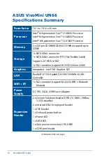
Page 10: ...D 1x M 2 connector support M 2 SSD 2242 or 2280 Graphics Integrated Intel HD Graphics 520 LAN Realtek 8111H Gigabit 10 100 1000 Mb s LAN Controller WIFI BT 1x M 2 connector support M 2 2230 WIFI Blutooth Module Power Supply DC 19V 3 42A 65W Power Adapter Expansion Header 2 x Custom Solutions header GPIO I2 C DMIC SMBus 3 3 5V standby 2 x Internal USB2 0 single port header 1 x CEC header 1 x Onboar...

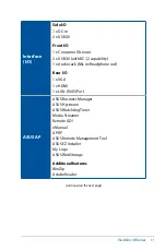
Page 11: ...ability 1 x Audio Jack Mic in Headphone out Rear I O 1 x VGA 1 x HDMI 1 x LAN RJ45 Port ASUS AP ASUS Business Manager ASUS Hystream ASUS Watchdog Timer Media Streamer Remote GO eManual APRP ASUS Remote Management Tool ASUS EZ Installer My Logo ASUS WebStorage Additional features WinZip Adobe Reader continued on the next page ...

Page 12: ...2 0 WfM 2 0 SM BIOS 2 7 ACPI 3 0 F12 Print Screen Last Modified Log Multi language BIOS Quick Note UEFI AMI BIOS PnP USB Boot device FDD ZIP HDD CDROM Select Boot Device by function key F8 during POST OS Support Windows 10 Pro 64 bit Windows 10 64 bit Windows 7 Professional 64 bit 32 bit NOTE Specifications are subject to change without notice ...

Page 13: ...2 Product Introduction Chapter 2 Product Introduction ...

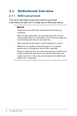
Page 14: ... a safely grounded object or a metal object such as the power supply case to avoid damaging them due to static electricity Hold components by the edges to avoid touching the ICs on them Whenever you uninstall any component place it on a grounded antistatic pad or in the bag that came with the component Before you install or remove any component ensure that the ATX power supply is switched off or t...

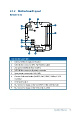
Page 15: ...ctor FFC Flat Flexible Cable 3 260 pin SO DIMM DDR4 2133 MHz 4 SATA 6Gb s connector power connector 5 2pin power connector 19V GND 6 Custom Solutions header 3xGPIO 2xI2 C DMIC SMBus 3 3 5V standby 7 COM port header 8 M 2 connector support M 2 2230 WIFI Blutooth Module 9 M 2 connector support M 2 SSD 2242 or 2280 Bottom view ...

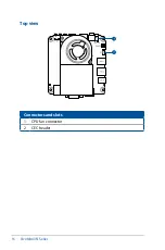
Page 16: ...16 VivoMini UN Series Connectors and slots 1 CPU fan connector 2 CEC header Top view ...

Page 17: ...VivoMini UN Series 17 Side view Bottom view 2 1 3 Motherboard dimensions ...

Page 18: ...18 VivoMini UN Series 2 1 4 System memory The motherboard comes with two 2 Double Data Rate 4 DDR4 Small Outline Dual Inline Memory Modules SODIMM slots ...

Page 19: ...orts Connect the USB module cable to any of these connectors These USB connectors comply with USB 2 0 specification that supports up to 480 Mbps connection speed 2 1 5 Internal connectors 2 COM port header 10 1 pin COM This connector is for the serial COM port Connect the serial port module cable to the connector ...

Page 20: ...rd is powered off and the presence of1 8V 3 3V and 5V standby power can be monitored with pins NOTE Ensure to use the bundled cable when connecting a hard disk drive to this connector 4 SATA 6Gb s connector power connector 7 pin SATA6G_1 5 pin SATA_PWR1 This connector connects to Serial ATA 6 Gb s hard disk drives via the Serial ATA 6 Gb s signal and power cable ...

Page 21: ...r connects to Serial ATA 6 Gb s hard disk drives via the Serial ATA 6 Gb s signal FCC cable NOTE Ensure to use the bundled cable when connecting a hard disk drive to this connector 6 Custom Solutions header 10 1 pin CUST1 CUST2 These connectors may be used to connect GPIO SMBus I2 C and DMIC signals ...

Page 22: ...upports 2230 WiFi modules 8 M 2 connector SOCKET3 The M 2 Socket 3 with M Key supports type 2242 22mm x 42mm and 2280 22mm x 80mm SSD modules NOTE Ensure to use the bundled screw pack to secure the M 2 module NOTE Ensure to use the bundled screw pack to secure the M 2 module ...

Page 23: ...e of the cable matches the BLACK WIRE pin of the connector WARNING DO NOT forget to connect the fan cables to the fan connector Insufficient air flow inside the system may damage the motherboard components These are not jumpers Do not place jumper caps on the fan connectors Ensure to fully insert the 4 pin CPU fan cable to the CPU fan connector ...

Page 24: ...i UN Series 10 CEC header 4 pin CEC This connector provides the standard communication signal from the HDMI connector allowing third part solutions to monitor or control CEC activity between multiple HDMI devices ...

Page 25: ...onnectors 7 8 Rear front and side panel connectors 1 LAN RJ 45 port 2 VGA port 3 HDMI port 4 Power input DC 19V 5 USB 3 0 ports with BC1 2 capability 6 Audio jack 7 USB 2 0 ports 8 Consumer IR sensor Rear panel Side panel Front panel ...

Page 26: ...26 VivoMini UN Series ...

Page 27: ...3 Upgrading your VivoMini ...

Page 28: ...to static electricity NOTE The illustrations in this chapter are for reference only The slots may vary depending on model To install or upgrade the memory modules 1 Turn off your VivoMini then disconnect all cables and peripherals 2 Place the VivoMini on a flat stable surface with its top side facing down Your VivoMini comes with two SO DIMM memory slots that allow you to install two 2GB 4GB 8GB o...

Page 29: ...29 3 Align and insert the memory module into the slot A and press it down B until it is securely seated in place Repeat the same steps to install the other memory module IMPORTANT Always install into the upper slot first ...

Page 30: ...r 2230 wireless and Bluetooth modules Refer to http www asus com for the list of compatible wireless and Bluetooth modules 1 Align and insert the wireless card into the lower slot inside the VivoMini 2 Gently push down the wireless card on top of the screw holes and fasten it using the bundled 3mm round screw ...

Page 31: ...antennas to your wireless card NOTE Connecting antennas to your wireless card may strengthen the wireless signal A soft clicking sound indicates that the antenna has been securely attached on the wireless card The antennas are purchased separately ...

Page 32: ...r VivoMini includes a M 2 slot that supports 2280 or 2242 M 2 SSD 3 3 1 To install or upgrade a 2242 M 2 SSD 1 Insert the bundled hexagon screw as illustrated 2 Align and insert the 2242 M 2 SSD into its slot inside the VivoMini Refer to the illustration for its location ...

Page 33: ...insert the 2280 M 2 SSD into its slot inside the VivoMini Refer to the illustration for its location 3 Gently push down the 2242 M 2 SSD on top of the screw hole and fasten it using one of the bundled 3mm round screws Refer to the illustration for the location of the screw hole ...

Page 34: ...34 VivoMini UN Series 2 Gently push down the 2280 M 2 SSD on top of the screw hole and fasten it using one of the bundled 3mm round screws Refer to the illustration for the location of the screw hole ...

Page 35: ...use the bundled Flat Flexible cable FFC SATA cable when installing an HDD or SSD to SATA6G_2 connector 3 4 1 To install the HDD or SSD using the FFC SATA cable 1 Connect the bundled FFC SATA cable to the HDD or SSD 2 Connect the bundled FFC SATA cable to your VivoMini ...

Page 36: ...ATA cable when installing an HDD or SSD to SATA6G_1 connector 3 4 2 To install the HDD or SSD using the SATA cable 1 Connect the bundled SATA cable to the HDD or SSD 2 Connect the bundled SATA cable to the SATA_PWR1 and SATA6G_1 connectors on your VivoMini ...

Page 37: ...4 BIOS Setup ...

Page 38: ... the BIOS setup You have installed a new system component that requires further BIOS settings or update 4 2 BIOS setup program Use the BIOS Setup program to update the BIOS or configure its parameters The BIOS screens include navigation keys and brief online help to guide you in using the BIOS Setup program Entering BIOS Setup at startup To enter BIOS Setup at startup Press Delete or F2 during the...

Page 39: ...stem settings Monitor For displaying the system temperature power status and changing the fan settings Boot For changing the system boot configuration Tool For configuring options for special functions Exit For selecting the exit options and loading default settings Menu items Submenu items General help Menu bar Last modified settings Displays the CPU temperature CPU voltage memory and voltage out...

Page 40: ... the menu bar contains the languages that you can select for your BIOS Click this button to select the language that you want to display in your BIOS screen Search on FAQ Move your mouse over this button to show a QR code scan this QR code on your mobile device to connect to the BIOS FAQ web page of the ASUS support website You can also scan the following QR code Quick Note F9 This button above th...

Page 41: ...l help At the bottom of the menu screen is a brief description of the selected item Use the F12 key to capture the BIOS screen and save it to the removable storage device Configuration fields These fields show the values for the menu items If an item is user configurable you can change the value of the field opposite the item You cannot select an item that is not user configurable A configurable f...

Page 42: ...n and allows you to set the system date time language and security settings Security The Security menu items allow you to change the system security settings NOTE The Administrator or User Password items on top of the screen show the default Not Installed After you set a password these items show Installed ...

Page 43: ...utious when changing the settings of the Advanced menu items Incorrect field values can cause the system to malfunction 4 4 1 Trusted Computing NOTE All values changed here do not take effect until computer is restarted Security Device Support Allows you to enable or disable the BIOS support for security device Configuration options Disable Enable ...

Page 44: ...sor package Configuration options All 1 IntelVirtualizationTechnology When set to Enabled a VMM can utilize the additional hardware capabilities provided by Vanderpool Technology Configuration options Disabled Enabled TPM State Allows you to enable or disable the security device Configuration options Disabled Enabled Pending operation Allows you to schedule an operation for the security device Con...

Page 45: ...chnology BIOS Extension Configuration options Disabled Enabled NOTE iAMT H W is always enabled This option just controls the BIOS extension execution If enabled this requires additional firmware in the SPI device BIOS Hotkey Pressed Allows you to enable or disable BIOS hotkey pressed Configuration options On Off Un Configure ME Allows you to Un Configure ME without a password Configuration options...

Page 46: ...p the BIOS automatically detects the presence of SATA devices The SATA Port items show Empty if no SATA device is installed to the corresponding SATA port Scroll down to display the other BIOS items TPM Device Selection Allows you to select the TPM device Configuration options dTPM 1 2 PTT WARNING When dTPM 1 2 is selected PTT dTPM will be disabled and all data saved on it will be lost ...

Page 47: ...ble PCIe port to SATA for RAID Remapping Configuration options Disabled Enabled Aggressive LPM Support This item is designed for LPM link power management support with a better energy saving conditions When set to Enabled the hot plug function of SATA ports are disabled Configuration options Disabled Enabled SMART SelfTest SMART Self Monitoring Analysis and Reporting Technology is a monitoring sys...

Page 48: ...d Enables the support for USB devices on legacy operating systems OS Auto Allows the system to detect the presence of USB devices at startup If detected the USB controller legacy mode is enabled If no USB device is detected the legacy USB support is disabled XHCI Hand off NOTE This item is set to Disabled by default for the EHCI enhanced host controller interface support by XHCI drivers in operati...

Page 49: ...y enabled Realtek LAN Controller This item allows you to enable or disable the Realtek LAN Controller Configuration options On Off Realtek PXE OPROM This item allows you to enable or disable the Realtek LAN preboot execution environment PXE option ROM Configuration options On Off Serial Port Configuration Allows you to set the parameters of Serial Port NOTE This item only functions if a serial por...

Page 50: ...abled S4 S5 Enabled S5 Restore AC Power Loss Power On The system goes into ON state after an AC power loss Power Off The system goes into OFF state after an AC power loss Last State The system goes into either OFF or ON state whatever the system state was before the AC power loss Power On By PCI E Allows you to enable or disable the wake on LAN function for the onboard LAN controller or other inst...

Page 51: ...ou to enable or disable UEFI Network Stack Configuration options Disabled Enabled NOTE The following items appear only when you set the Network Stack to Enabled Ipv4 PXE Support Enables or disables the Ipv4 PXE Boot Support If disabled Ipv4 PXE boot option will not be created Configuration options Disabled Enabled Ipv6 PXE Support Enables or disables the Ipv6 PXE Boot Support If disabled Ipv6 PXE ...

Page 52: ...to accelerate the boot speed NOTE The following item appears only when you set the Fast Boot to Enabled 4 5 Monitor menu The Monitor menu displays the system temperature power status and allows you to change the fan settings when the items are set to Monitor Selecting Ignore will not display any status values 4 6 Boot menu The Boot menu items allow you to change the system boot options Scroll down...

Page 53: ...econds or until ESC is pressed NOTE The following items appears only when you set the Boot Logo Display item to Full Screen or Auto Post Delay Time This item This item allows you to select a desired additional POST waiting time to easily enter the BIOS Setup You can only execute the POST delay time during normal boot The values range from 0 to 10 seconds NOTE This feature only works when set under...

Page 54: ...acy OPROM Legacy OPROM only UEFI only Boot from Network Devices Legacy only This item allows you to select the type of network devices that you want to launch Configuration options Ignore Legacy only UEFI driver first Secure Boot This item allows you to configure the Windows Secure Boot settings and manage its keys to protect the system from unauthorized access and malwares during POST OS Type Win...

Page 55: ...item allows you to delete the PK from your system Once the PK is deleted all the system s Secure Boot keys will not be active Configuration options Yes No KEK Management NOTE Key exchange Key KEK refers to Microsoft Secure Boot Key Enrollment Key KEK Set New Key Allows you to load the downloaded KEK from a USB storage device Append Key Allows you to load the additional KEK from a storage device fo...

Page 56: ...SB storage device Configuration options Yes No Append Key Allows you to load the additional dbx from a storage device so that more db s images cannot be loaded Delete Key Allows you to delete the dbx file from your system NOTE The dbx file must be formatted as a UEFI variable structure with time based authenticated variable Boot Option Priorities These items specify the boot device priority sequen...

Page 57: ... 7 1 ASUS EZ Flash 3 Utility Allows you to run ASUS EZ Flash 3 When you press Enter a confirmation message appears Use the Left Right arrow key to select between via Storage Devices s or via Internet then press Enter to confirm your choice NOTE For more details refer to section 4 9 2 ASUS EZ Flash 3 utility 4 7 2 ASUS SPD Information Allows you to view the DRAM SPD information DIMM slot number All...

Page 58: ...es Reset Once you are finished making your selections choose this option from the Exit menu to ensure the values you selected are saved When you select this option or if you press F10 a confirmation window appears SelectYes to save changes and exit Discard Changes Exit This option allows you to exit the Setup program without saving your changes When you select this option or if you press Esc a con...

Page 59: ...download the latest BIOS file for this motherboard The following utilities allow you to manage and update the motherboard BIOS setup program 1 EZ Update Updates the BIOS in Windows environment 2 ASUS EZ Flash 3 Updates the BIOS using a USB flash drive 3 ASUS CrashFree BIOS 3 Restores the BIOS using the motherboard support USB drive when the BIOS file fails or gets corrupted 4 9 1 EZ Update The EZ ...

Page 60: ...ernet connection before updating through the Internet To update the BIOS by USB 1 Insert the USB flash disk that contains the latest BIOS file to the USB port 2 Go to the Tool menu to select ASUS EZ Flash 3 Utility and press Enter 3 Select via Storage Device s and press Enter 4 Press Tab to switch to the Drive field 5 Press the Up Down arrow keys to find the USB flash disk that contains the latest...

Page 61: ...his function can support devices such as a USB flash disk with FAT 32 16 format and single partition only DO NOT shut down or reset the system while updating the BIOS to prevent system boot failure IMPORTANT Ensure to load the BIOS default settings to ensure system compatibility and stability Select the Load Optimized Defaults item under the Exit menu See section 4 8 Exit Menu for details ...

Page 62: ...Right arrow keys to select an Internet connection method and then press Enter 4 Follow the onscreen instructions to complete the update 5 Reboot the system when the update process is done IMPORTANT Ensure to load the BIOS default settings to ensure system compatibility and stability Select the Load Optimized Defaults item under the Exit menu See section 4 8 Exit Menu for details ...

Page 63: ...OS file download the file at https www asus com support and save it to a USB flash drive To recover the BIOS 1 Turn on the system 2 Insert the motherboard support USB drive or a USB flash drive containing the BIOS file to the USB port 3 The utility automatically checks the devices for the BIOS file When found the utility reads the BIOS file and enters the ASUS EZ Flash 3 Utility automatically 4 Th...

Page 64: ...64 VivoMini UN Series ...

Page 65: ...Appendix ...

Page 66: ...n Do not block or cover these openings Make sure you leave plenty of space around the system for ventilation Never insert objects of any kind into the ventilation openings Use this product in environments with ambient temperatures between 0 C and 35 C If you use an extension cord make sure that the total ampere rating of the devices plugged into the extension cord does not exceed its ampere rating...

Page 67: ...se of parts and recycling This symbol of the crossed out wheeled bin indicates that the product electrical electronic equipment and mercury containing button cell battery should not be placed in municipal waste Check local technical support services for product recycling If you encounter the following technical problems with the product unplug the power cord and contact a qualified service technic...

Page 68: ...except on the areas where the I O ports are located Federal Communications Commission Statement This device complies with Part 15 of the FCC Rules Operation is subject to the following two conditions This device may not cause harmful interference and This device must accept any interference received including interference that may cause undesired operation This equipment has been tested and found ...

Page 69: ...tter must be installed to provide a separation distance of at least 20 cm from all persons and must not be co located or operating in conjunction with any other antenna or transmitter End users and installers must be provide with antenna installation instructions and transmitter operating conditions for satisfying RF exposure compliance Declaration of Conformity R TTE directive 1999 5 EC Replaced ...

Page 70: ...e 2446 5 2483 5 MHz band Use outdoors on public property is not permitted In the departments listed below for the entire 2 4 GHz band Maximum authorized power indoors is 100mW Maximum authorized power outdoors is 10mW Departments in which the use of the 2400 2483 5 MHz band is permitted with an EIRP of less than 100mW indoors and less than 10mW outdoors 01 Ain 02 Aisne 03 Allier 05 Hautes Alpes 08...

Page 71: ...dian Department of Communications This class B digital apparatus complies with Canadian ICES 003 IC Radiation Exposure Statement for Canada This equipment complies with IC radiation exposure limits set forth for an uncontrolled environment To maintain compliance with IC RF exposure compliance requirements please avoid direct contact to the transmitting antenna during transmitting End users must fo...

Page 72: ...omplies with the requirements of Directive 1999 5 EC replaced in 2017 by RED 2014 53 EU of the European Parliament and Commission from 9 March 1999 governing Radio and Telecommunications Equipment and mutual recognition of conformity Wireless Operation Channel for Different Domains N America 2 412 2 462 GHz Ch01 through CH11 Japan 2 412 2 484 GHz Ch01 through Ch14 Europe ETSI 2 412 2 472 GHz Ch01 ...

Page 73: ...e http usa asus com Technical Support Support fax 1 812 284 0883 General support 1 812 282 2787 Online support http qr asus com techserv ASUS COMPUTER GmbH Germany and Austria Address Harkort Str 21 23 D 40880 Ratingen Germany Fax 49 2102 959931 Web site http www asus com de Online contact http eu rma asus com sales Technical Support Telephone 49 2102 5789555 Support Fax 49 2102 959911 Online supp...

Page 74: ...74 VivoMini UN Series ...

Reviews: