2-30
Chapter 2: Hardware information
4.
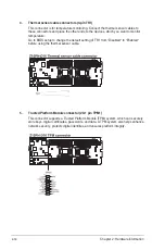
Thermal sensor cable connectors (3-pin TR1)
This connector is for temperature monitoring. Connect the thermal sensor cables to
these connectors and place the other ends to the devices, which you want to monitor
temperature.
Go to BIOS setup to change the default setting of TR1 from “Disabled“ to “Enabled“
before using the thermal sensor cable.
5.
Trusted Platform Module connector (20-1 pin TPM1)
This connector supports a Trusted Platform Module (TPM) system, which can securely
store keys, digital certificates, passwords, and data. A TPM system also helps enhance
network security, protects digital identities, and ensures platform integrity.
Summary of Contents for Z10PH-D16
Page 1: ...Z10PH D16 Server Motherboard User Guide ...
Page 14: ...xiv ...
Page 22: ...2 4 Chapter 2 Hardware information 2 2 3 Z10PH D16 Motherboard layout ...
Page 58: ...2 40 Chapter 2 Hardware information ...
Page 62: ...3 4 Chapter 3 Powering up ...
Page 152: ...5 38 Chapter 5 RAID configuration ...
Page 180: ...A 2 Appendix A Reference information A 1 Z10PH D16 block diagram ...


