background image

Motherboard

Z8NR-D12

Summary of Contents for Z8NR-D12 - Motherboard - SSI EEB 3.61

Page 1: ...Motherboard Z8NR D12 ...

Page 2: ...ERCHANTABILITY OR FITNESS FOR A PARTICULAR PURPOSE IN NO EVENT SHALL ASUS ITS DIRECTORS OFFICERS EMPLOYEES OR AGENTS BE LIABLE FOR ANY INDIRECT SPECIAL INCIDENTAL OR CONSEQUENTIAL DAMAGES INCLUDING DAMAGES FOR LOSS OF PROFITS LOSS OF BUSINESS LOSS OF USE OR DATA INTERRUPTION OF BUSINESS AND THE LIKE EVEN IF ASUS HAS BEEN ADVISED OF THE POSSIBILITY OF SUCH DAMAGES ARISING FROM ANY DEFECT OR ERROR I...

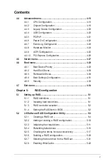
Page 3: ...2 1 Placement direction 2 2 2 2 2 Screw holes 2 2 2 2 3 Motherboard layouts 2 3 2 2 4 Layout contents 2 4 2 3 Central Processing Unit CPU 2 6 2 3 1 Installing the CPU 2 6 2 3 2 Installing the CPU heatsink and fan 2 9 2 4 System memory 2 11 2 4 1 Overview 2 11 2 4 2 Memory configurations 2 12 2 4 3 Installing a DIMM 2 13 2 4 4 Removing a DIMM 2 13 2 5 Expansion slots 2 14 2 5 1 Installing an expans...

Page 4: ...r switch 3 2 Chapter 4 BIOS setup 4 1 Managing and updating your BIOS 4 1 4 1 1 AFUDOS utility 4 1 4 1 2 ASUS CrashFree BIOS 3 utility 4 3 4 2 BIOS setup program 4 4 4 2 1 BIOS menu screen 4 5 4 2 2 Menu bar 4 5 4 2 3 Navigation keys 4 5 4 2 4 Menu items 4 6 4 2 5 Sub menu items 4 6 4 2 6 Configuration fields 4 6 4 2 7 Pop up window 4 6 4 2 8 Scroll bar 4 6 4 2 9 General help 4 6 4 3 Main menu 4 7...

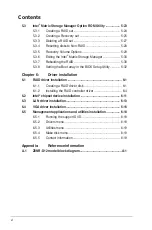
Page 5: ...rives 4 30 4 6 4 Boot Settings Configuration 4 31 4 6 5 Security 4 32 4 7 Exit menu 4 34 Chapter 5 RAID configuration 5 1 Setting up RAID 5 1 5 1 1 RAID definitions 5 1 5 1 2 Installing hard disk drives 5 1 5 1 3 RAID controller selection 5 2 5 1 4 Setting the RAID item in BIOS 5 2 5 2 LSI Software RAID Configuration Utility 5 3 5 2 1 Creating a RAID set 5 4 5 2 2 Adding or viewing a RAID configur...

Page 6: ... the BIOS Setup Utility 5 32 Chapter 6 Driver installation 6 1 RAID driver installation 6 1 6 1 1 Creating a RAID driver disk 6 1 6 1 2 Installing the RAID controller driver 6 4 6 2 Intel chipset device installation 6 11 6 3 LAN driver installation 6 13 6 4 VGA driver installation 6 16 6 5 Management applications and utilities installation 6 18 6 5 1 Running the support DVD 6 18 6 5 2 Drivers menu...

Page 7: ...ause harmful interference to radio or television reception which can be determined by turning the equipment off and on the user is encouraged to try to correct the interference by one or more of the following measures Reorient or relocate the receiving antenna Increase the separation between the equipment and receiver Connect the equipment to an outlet on a circuit different from that to which the...

Page 8: ...efore installing the motherboard and adding devices on it carefully read all the manuals that came with the package Before using the product make sure all cables are correctly connected and the power cables are not damaged If you detect any damage contact your dealer immediately To avoid short circuits keep paper clips screws and staples away from connectors slots sockets and circuitry Avoid dust ...

Page 9: ...s Detailed descriptions of the BIOS parameters are also provided Chapter 5 RAID configuration This chapter provides instructions for setting up creating and configuring RAID sets using the available utilities Chapter 6 Driver installation This chapter provides instructions for installing the necessary drivers for different system components Appendix Reference information This appendix includes add...

Page 10: ...key Key1 Key2 Key3 If you must press two or more keys simultaneously the key names are linked with a plus sign Example Ctrl Alt D Command Means that you must type the command exactly as shown then supply the required item or value enclosed in brackets Example At the DOS prompt type the command line format A S DANGER WARNING Information to prevent injury to yourself when trying to complete a task C...

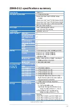
Page 11: ...1333 Reg DIMM Unbuffered DIMM with ECC non ECC Memory Size 1 GB 2GB 4GB 8GB Expansion Slots follow SSI Location Total PCI PCI X PCI E Slots 5 Slot Location 1 1 x PCI 32bit 33MHz Slot Location 3 1 x PCIe x8 Gen2 x4 Link Slot Location 4 1 x PCIe x8 Gen2 x4 Link Slot Location 5 1 x PCIe x8 Gen2 x8 Link Slot Location 6 1 x PCIe x16 Gen2 x16 Link for 1U Full Hight Half Length Card Auto switch to x8 Lin...

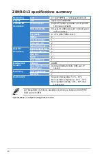
Page 12: ...er connector USB Connectors 3 support 4 USB ports and 1 internal Type A USB connector Fan Header 8 4Pin With PWM control SMBus 2 Chassis Intruder 1 Front LAN LED 2 Serial Port Header 1 Rear I O Connectors External Serial Port 1 External USB Port 2 VGA Port 1 RJ 45 2 PS 2 KB Mouse 1 Management Solution Software ASWM Out of Band Remote Management Optional ASMB4 iKVM for KVM over IP support Monitorin...

Page 13: ...1 Product introduction This chapter describes the motherboard features and the new technologies it supports ...

Page 14: ...ASUS Z8NR D12 Chapter summary 1 1 1 Welcome 1 1 1 2 Package contents 1 1 1 3 Serial number label 1 2 1 4 Special features 1 2 ...

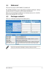
Page 15: ...ove items is damaged or missing contact your retailer Standard Gift Box Pack Standard Bulk Pack Z8NR D12 Z8NR D12 Cables SATA signal cable 6 FDD cable 1 Accessories IO shield 1 1 Application CD Support CD 1 1 Documentation User Guide 1 1 Packing Qty 1 pcs per carton 10 pcs per carton Optional items Description PIKE 1064E LSI 4 port SAS RAID card PIKE 1068E LSI 8 port SAS RAID card PIKE 1078 LSI 8 ...

Page 16: ...ces higher processing throughout and improved performance on today s multi threaded software DDR3 memory support The Z8NR D12 supports UDIMM and RDIMM DDR3 memory that features data transfer rates of 1333 1066 MHZ to meet the higher bandwidth requirements of server and workstation applications The 3 channel DDR3 architecture boosts system performance eliminating bottlenecks with peak bandwidth of ...

Page 17: ...y EIST intelligently manages the CPU resources by automatically adjusting the CPU voltage and core frequency depending on the CPU loading and system speed or power requirement Serial ATA II technology The motherboard supports the Serial ATA II 3 Gb s technology through ICH10R Serial ATA interfaces The Serial ATA II specification provides twice the bandwidth of the current Serial ATA products with ...

Page 18: ...y adjusts the fan speeds according to the system loading to ensure quiet cool and efficient operation PIKE Proprietary I O Kit Expansion PIKE is an on demand upgrade kit for users This ASUS unique feature enables users to choose their preferred I O solutions ASUS provides multiple SAS solutions for different segments and purposes and PIKE saves lots of validation efforts and hardware cost for end ...

Page 19: ... Hardware information This chapter lists the hardware setup procedures that you have to perform when installing system components It includes description of the jumpers and connectors on the motherboard ...

Page 20: ...S Z8NR D12 Chapter summary 2 2 1 Before you proceed 2 1 2 2 Motherboard overview 2 2 2 3 Central Processing Unit CPU 2 6 2 4 System memory 2 11 2 5 Expansion slots 2 14 2 6 Jumpers 2 18 2 7 Connectors 2 23 ...

Page 21: ...h as the power supply case before handling components to avoid damaging them due to static electricity Hold components by the edges to avoid touching the ICs on them Whenever you uninstall any component place it on a grounded antistatic pad or in the bag that came with the component Before you install or remove any component ensure that the power supply is switched off or the power cord is detache...

Page 22: ...ving the motherboard Failure to do so can cause you physical injury and damage motherboard components 2 2 1 Placement direction When installing the motherboard ensure that you place it into the chassis in the correct orientation The edge with external ports goes to the rear part of the chassis as indicated in the image below 2 2 2 Screw holes Place nine 9 screws into the holes indicated by circles...

Page 23: ...ASUS Z8NR D12 2 3 2 2 3 Motherboard layouts ...

Page 24: ...r setting 3 pin LAN_SW1 LAN_SW2 2 19 4 iBTN RAID setting 3 pin IBTN_SEL1 2 20 5 RAID configuration utility selection 3 pin RAID_SEL1 2 20 6 Force BIOS recovery setting 3 pin RECOVERY1 2 21 7 Fan controller setting 3 pin FAN_SEL1 2 22 8 DDR3 voltage setting 4 pin LVDDR3_SEL1 2 2 22 Rear panel connectors Page 1 PS 2 mouse port green 2 23 2 RJ 45 port for iKVM 2 23 3 PS 2 keyboard port purple 2 23 4 ...

Page 25: ...al General Purpose Input Output connectors 6 1 pin SGPIO2 3 2 26 7 USB connectors 10 1 pin USB34 USB56 4 pin USB7 2 27 8 CPU and system fan connectors 4 pin CPU_FAN1 2 REAR_FAN1 2 FRNT_FAN1 2 3 4 2 27 9 Serial port connectors 10 1 pin COM2 2 28 10 Power supply SMBus connector 5 pin PSUSMB1 2 28 11 SSI power connectors 24 pin ATXPWR1 8 pin ATX12V1 2 2 29 12 Baseboard Management Controller BMC conne...

Page 26: ...s on the socket and the socket contacts are not bent Contact your retailer immediately if the PnP cap is missing or if you see any damage to the PnP cap socket contacts motherboard components ASUS will shoulder the cost of repair only if the damage is shipment transit related Keep the cap after installing the motherboard ASUS will process Return Merchandise Authorization RMA requests only if the m...

Page 27: ...oad lever with your thumb A then move it to the left B until it is released from the retention tab A B Load lever Retention tab 3 Lift the load lever in the direction of the arrow to a 135º angle 4 Lift the load plate with your thumb and forefinger to a 100º angle Load plate 4 3 5 Remove the PnP cap from the CPU socket PnP cap ...

Page 28: ...PU notch 7 Apply some Thermal Interface Material to the exposed area of the CPU that the heatsink will be in contact with ensuring that it is spread in an even thin layer Some heatsinks come with pre applied thermal paste If so skip this step DO NOT eat the Thermal Interface Material If it gets into your eyes or touches your skin ensure that you wash it off immediately and seek professional medica...

Page 29: ...items that are necessary for CPU installation Ensure that you have applied the thermal grease to the top of the CPU before installing the heatsink and fan Refer to the installation manual that came with the CPU package for details on heatsink fan assembly and installation To install the CPU heatsink and fan 1 Place the heatsink on top of the installed CPU ensuring that the four screws on the heats...

Page 30: ...re monitoring errors may occur if you fail to plug this connector 4 Repeat steps 1 to 3 to install the other heatsink if you have installed a second CPU then connect the fan cable to the nearest 4 pin fan connector 3 Connect the fan cable to the nearest 4 pin fan connector FAN connector ...

Page 31: ...ulated Populated Populated Populated 6 DIMMs Populated Populated Populated Populated Populated Populated Due to Intel CPU spec definition the system will not boot if only one DIMM is installed in DIMM slot A2 B2 or C2 for CPU1 or D2 E2 or F2 for CPU2 Follow the table above for recommended memory configuration Recommended CPU2 memory configuration Mode Sockets DIMM_D1 DIMM_D2 DIMM_E1 DIMM_E2 DIMM_F...

Page 32: ...Channel A Channel B and Channel C The system maps the total size of the lower sized channel for the dual channel or triple channel configuration Any excess memory from the higher sized channel is then mapped for single channel operation Due to the memory address limitation on 32 bit Windows OS when you install 4GB or more memory on the motherboard the actual usable memory for the OS can be about 3...

Page 33: ...t until the retaining clips snap back in place and the DIMM is properly seated Ensure to unplug the power supply before adding or removing DIMMs or other system components Failure to do so may cause severe damage to both the motherboard and the components A DIMM is keyed with a notch so that it fits in only one direction DO NOT force a DIMM into a socket to avoid damaging the DIMM Unlocked retaini...

Page 34: ...se Keep the screw for later use 4 Align the card connector with the slot and press firmly until the card is completely seated on the slot 5 Secure the card to the chassis with the screw you removed earlier 6 Replace the system cover 2 5 2 Configuring an expansion card After installing the expansion card configure the it by adjusting the software settings 1 Turn on the system and change the necessa...

Page 35: ... 1 2 Keyboard Controller 2 Programmable Interrupt 3 11 Communications Port COM2 4 12 Communications Port COM1 5 13 6 14 Floppy Disk Controller 7 15 8 3 System CMOS Real Time Clock 9 4 ACPI Mode when used 10 5 IRQ Holder for PCI Steering 11 6 IRQ Holder for PCI Steering 12 7 PS 2 Compatible Mouse Port 13 8 Numeric Data Processor 14 9 Primary IDE Channel 15 10 Secondary IDE Channel ...

Page 36: ... link to the 5500 IOH These slots are designed for various server class high performance add on cards like SCSI RAID card fiber channel card etc 2 5 6 PCI slot The PCI slot supports cards such as a LAN card USB card and other cards that comply with PCI 2 3 specifications 2 5 7 PIKE slot The PIKE slot allows you to choose and change your preferred SAS solution easily Install an optional ASUS PIKE R...

Page 37: ...e motherboard 2 Align the golden fingers of the RAID card with the PIKE RAID card slot 3 Insert the RAID card into the PIKE RAID card slot Ensure that it is completely seated on the PIKE RAID card slot 2 5 9 Installing i Button Follow the steps below to install an optional i Button on your motherboard 1 Locate the I Button slot on the motherboard 2 Snap the I Button in place ...

Page 38: ... computer and unplug the power cord 2 Move the jumper cap from pins 1 2 default to pins 2 3 Keep the cap on pins 2 3 for about 5 10 seconds then move the cap back to pins 1 2 3 Plug the power cord and turn ON the computer 4 Hold down the Del key during the boot process and enter BIOS setup to re enter data Except when clearing the RTC RAM never remove the cap on CLRTC jumper default position Remov...

Page 39: ...enable or disable the onboard VGA controller Set to pins 1 2 to activate the VGA feature 3 LAN controller setting 3 pin LAN_SW1 LAN_SW2 These jumpers allow you to enable or disable the onboard Intel WG82574L Gigabit LAN1 2 controller Set to pins 1 2 to activate the Gigabit LAN feature ...

Page 40: ... RAID setting 3 pin IBTN_SEL1 This jumper allows you to select the RAID configuration utility to use when you create disk arrays Place the jumper caps on pins 1 2 if you install a PIKE RAID card to the motherboard and want to use the LSI Logic MPT Setup Utility default Or you can place the jumper caps on pins 2 3 to create the LSI Mega RAID 5 by supported Intel ICH10R SATA controller LSI Logic MPT...

Page 41: ...date the BIOS 1 Prepare a floppy disk that contains the original or latest BIOS for the motherboard XXXXXX ROM and the AFUDOS EXE utility 2 Set the jumper to pins 2 3 3 Insert the floppy disk then turn on the system to update the BIOS 4 Shut down the system 5 Set the jumper back to pins 1 2 6 Turn on the system Use the AFUDOS uitility version 2 38 to flash the BIOS ...

Page 42: ... use a 3 pin fan but set the jumper for a 4 pin fan the fan controll will not work and the fan you installed will always run at full speed 8 DDR3 voltage setting 4 pin LVDDR3_SEL1 2 These jumpers allow you to select DDR3 DIMM voltage settings Place the jumper caps on pins 1 2 if you want to control DDR3 voltage by BIOS settings default Place the jumper caps on pins 2 3 to force the DDR3 DIMMs to r...

Page 43: ...r serial devices 6 Video Graphics Adapter port This port is for a VGA monitor or other VGA compatible devices 7 LAN 1 RJ 45 port This port allows Gigabit connection to a Local Area Network LAN through a network hub Refer to the table below for the LAN port LED indications 8 LAN 2 RJ 45 port This port allows Gigabit connection to a Local Area Network LAN through a network hub Refer to the table bel...

Page 44: ... 34 1 pin FLOPPY1 This connector is for the floppy disk drive FDD signal cable Insert one end of the cable to this connector then connect the other end to the signal connector at the back of the floppy disk drive Pin 5 on the connector is removed to prevent incorrect cable connection when using a FDD cable with a covered Pin 5 Ensure to install the ICH10R RAID driver from the support DVD during OS...

Page 45: ... eight 8 Serial Attached SCSI SAS connectors the next generation storage technology that supports both Series SCSI and Serial ATA SATA Each connector supports one device These connectors function only when you install a PIKE RAID card Connect the SAS hard disk drives to SAS connectors 1 4 red when installing a 4 port PIKE RAID card Ensure to install the PIKE RAID driver during OS installation afte...

Page 46: ...eripherals for the LSI embedded SATA RAID or Intel Matrix RAID 6 Serial General Purpose Input Output connectors 6 1 pin SGPIO2 3 These connector is used for the SAS chip SIO interface that controls the LED pattern generation device information and general purpose data These connectors functions only when you install a PIKE SAS RAID card ...

Page 47: ... speed The USB port module is purchased separately 8 CPU and system fan connectors 4 pin CPU_FAN1 2 REAR_FAN1 2 FRNT_FAN1 2 3 4 The fan connectors support cooling fans of 350 mA 740 mA 8 88 W max or a total of 3 15 A 6 66 A 53 28 W max at 12V Connect the fan cables to the fan connectors on the motherboard making sure that the black wire of each cable matches the ground pin of the connector DO NOT ...

Page 48: ...nect the serial port module cable to this connector then install the module to a slot opening at the back of the system chassis The serial port module is purchased separately 10 Power supply SMBus connector 5 pin PSUSMB1 This connector is for the power supply SMB cable if your power supply supports the SMBus function ...

Page 49: ... socket Intel Xeon processors DO NOT forget to connect the 24 8 8 pin power plugs otherwise the system will not boot up Use of a PSU with a higher power output is recommended when configuring a system with more power consuming devices The system may become unstable or may not boot up if the power is inadequate You must install a PSU with a higher power rating if you intend to install additional de...

Page 50: ...n SPEAKER This 4 pin connector is for the chassis mounted system warning speaker The speaker allows you to hear system beeps and warnings 4 Hard disk drive activity LED 2 pin IDE_LED This 2 pin connector is for the HDD Activity LED Connect the HDD Activity LED cable to this connector The IDE LED lights up or flashes when data is read from or written to the HDD 5 ATX power button soft off button 2 ...

Page 51: ...tion feature for chassis with intrusion sensor or microswitch When you remove any chassis component the sensor triggers and sends a high level signal to these leads to record a chassis intrusion event The default setting is short CASEOPEN and GND pin by jumper cap to disable the function 4 Locator LED 2 pin LOCATORLED1 and 2 pin LOCATORLED2 These leads are for the locator LED1 and LED2 on the fron...

Page 52: ...2 32 Chapter 2 Hardware information ...

Page 53: ...3 Powering up This chapter describes the power up sequence and ways of shutting down the system ...

Page 54: ...ASUS Z8NR D12 Chapter summary 3 3 1 Starting up for the first time 3 1 3 2 Turning off the computer 3 2 ...

Page 55: ...p or switch between orange and green after the system LED turns on The system then runs the power on self tests or POST While the tests are running the BIOS beeps see BIOS beep codes table below or additional messages appear on the screen If you do not see anything within 30 seconds from the time you turned on the power the system may have failed a power on test Check the jumper settings and conne...

Page 56: ...ts down If you are using Windows XP 1 Click the Start button then select Turn Off Computer 2 Click the Turn Off button to shut down the computer 3 The power supply should turn off after Windows shuts down 3 2 2 Using the dual function power switch While the system is ON pressing the power switch for less than four seconds puts the system to sleep mode or to soft off mode depending on the BIOS sett...

Page 57: ...4 BIOS setup This chapter tells how to change the system settings through the BIOS Setup menus Detailed descriptions of the BIOS parameters are also provided ...

Page 58: ...Chapter summary 4 ASUS Z8NR D12 4 1 Managing and updating your BIOS 4 1 4 2 BIOS setup program 4 4 4 3 Main menu 4 7 4 4 Advanced menu 4 13 4 5 Server menu 4 27 4 6 Power menu 4 29 4 7 Exit menu 4 34 ...

Page 59: ...s corrupted during the updating process Copying the current BIOS To copy the current BIOS file using the AFUDOS utility Ensure that the USB flash drive is not write protected and has at least 2048 KB free space to save the file The succeeding BIOS screens are for reference only The actual BIOS screen displays may not be the same as shown 1 Copy the AFUDOS utility afudos exe from the motherboard su...

Page 60: ...are Update Utility Version 1 19 ASUS V2 07 03 11 24BB Copyright C 2002 American Megatrends Inc All rights reserved WARNING Do not turn off power during flash BIOS Reading file done Reading flash done Advance Check Erasing flash done Writing flash 0x0008CC00 9 The utility verifies the file and then starts updating the BIOS file DO NOT shut down or reset the system while updating the BIOS to prevent...

Page 61: ...r the BIOS using ASUS CrashFree BIOS 3 1 Insert the USB flash disk that contains the BIOS file to the USB port 2 Turn on the system 3 The utility will automatically checks the devices for the BIOS file When found the utility reads the BIOS file and starts flashing the corrupted BIOS file 4 Restart the system after the utility completes the updating process DO NOT shut down or reset the system whil...

Page 62: ...am Press Del during the Power On Self Test POST to enter the Setup utility otherwise POST continues with its test routines If you wish to enter Setup after POST restart the system by pressing Ctrl Alt Delete or by pressing the reset button on the system chassis You can also restart by turning the system off and then back on Do this last option only if the first two failed The Setup program is desi...

Page 63: ... menu Use the navigation keys to select items in the menu and change the settings 4 2 1 BIOS menu screen Some of the navigation keys differ from one screen to another v02 61 C Copyright 1985 2008 American Megatrends Inc BIOS SETUP UTILITY Main Advanced Server Boot Exit Use ENTER TAB or SHIFT TAB to select a field Use or to configure system Date Select Screen Select Item Change Field Tab Select Fie...

Page 64: ...pop up window with the configuration options for that item 4 2 8 Scroll bar A scroll bar appears on the right side of a menu screen when there are items that do not fit on the screen Press the Up Down arrow keys or Page Up Page Down keys to display the other items on the screen 4 2 9 General help At the top right corner of the menu screen is a brief description of the selected item v02 61 C Copyri...

Page 65: ... MB 3 5 in Refer to section 4 2 1 BIOS menu screen for information on the menu screen items and how to navigate through them v02 61 C Copyright 1985 2008 American Megatrends Inc BIOS SETUP UTILITY Main Advanced Server Boot Exit Use ENTER TAB or SHIFT TAB to select a field Use or to configure system Date System Time 13 44 30 System Date Tue 11 04 2008 Legacy Diskette A 1 44M 3 5 in SATA 1 ST3160812...

Page 66: ...LBA mode Setting to Auto enables the LBA mode if the device supports this mode and if the device was not previously formatted with LBA mode disabled Configuration options Disabled Auto Block Multi Sector Transfer M Auto Enables or disables data multi sectors transfers When set to Auto the data transfer from and to the device occurs multiple sectors at a time if the device supports multi sector tra...

Page 67: ...MA mode Configuration options Auto SWDMA0 SWDMA1 SWDMA2 MWDMA0 MWDMA1 MWDMA2 UDMA0 UDMA1 UDMA2 UDMA3 UDMA4 UDMA5 S M A R T Auto Sets the Smart Monitoring Analysis and Reporting Technology Configuration options Auto Disabled Enabled 32Bit Data Transfer Enabled Enables or disables 32 bit data transfer Configuration options Disabled Enabled ...

Page 68: ...tem to AHCI The AHCI allows the onboard storage driver to enable advanced Serial ATA features that increases storage performance on random workloads by allowing the drive to internally optimize the order of commands If you want to create a RAID 0 RAID 1 RAID 5 RAID 10 or the Intel Matrix Storage Technology configuration from the Serial ATA hard disk drives set this item to RAID Hard Disk Write Pro...

Page 69: ... options 0 5 10 15 20 25 30 35 SATA Port1 6 XXXX Displays the status of auto detection of SATA devices 4 3 6 AHCI Configuration This menu is the section for AHCI configuration BIOS SETUP UTILITY Main AHCI Settings AHCI CD DVD Boot Time out 35 SATA Port1 Not Detected SATA Port2 Not Detected SATA Port3 Not Detected SATA Port4 Not Detected SATA Port5 Not Detected SATA Port6 Not Detected Some SATA CD ...

Page 70: ...unt 1 System Memory Usable Size 1023MB System Memory Information AMIBIOS Displays the auto detected BIOS information Processor Displays the auto detected CPU specification System Memory Displays the auto detected system memory System Memory Information Displays system memory information BIOS SETUP UTILITY Main AMIBIOS CPU1 Memory Configuration CPU2 Memory Configuration CPU1 2 Memory Configuration ...

Page 71: ...TILITY Advanced Configure advanced CPU settings Module Version 3F 11 Manufacturer Intel Brand String Genuine Intel R CPU 0000 2 67GHz Frequency 2 66GHz BCLK Speed 133MHz Cache L1 128 KB Cache L2 1024 KB Cache L3 8192 KB Ratio Status Unlocked Min 12 Max 20 Ratio Actual Value 20 CPUID 106A2 Ratio CMOS Setting Auto C1E Support Enabled Hardware Prefetcher Enabled Adjacent Cache Line Prefetch Enabled I...

Page 72: ...a hardware platform to run multiple operating systems separately and simultaneously enabling one system to virtually function as several systems Configuration options Disabled Enabled CPU TM Function Enabled This function enables the overheated CPU to throttle the clock speed to cool down Configuration options Disabled Enabled Execute Disable Bit Capability Enabled Allows you to enable or disable ...

Page 73: ...te Technology allows the CPU to save more power under idle mode Enable this item only when you install a C State Technology supported CPU Configuration options Disabled Enabled C3 State ACPI C2 Allows you to select the CPU action under C3 state Configuration options Disabled ACPI C2 ACPI C3 C6 7 State Enabled Allows you to select the CPU action under C6 and C7 state Configuration options Disabled ...

Page 74: ...ave and Exit ESC Exit Configure North Bridge features CPU Bridge Chipset Configuration v02 61 C Copyright 1985 2008 American Megatrends Inc BIOS SETUP UTILITY Advanced CPU Bridge Chipset Configuration CPU REVISION B0 Current CSI Frequency 6 400GT Current Memory Frequency 1066 Mhz CSI Links Speed Full Speed CSI Frequency Auto CSI Isochronous Disabled CSI L0s Disabled CIS L1 Disabled Memory Frequenc...

Page 75: ...e system to detect DDR3 memory frequency via SPD or designate a specific frequency Configuration options Auto Force DDR 800 Force DDR 1066 Force DDR 1333 Memory Mode Independent Allows you to set Memory channel mode Configuration options Independent Channel Mirroring Lockstep Sparing Memory ECC Function Enabled Allows you to enable or disable the memory ECC function Configuration options Disabled ...

Page 76: ...onfiguration options Closed Open Adaptive Page Disabled Configuration options Disabled Enabled Data Scramble Enabled Configuration options Disabled Enabled Split Below 4GB Disabled Configuration options Disabled Auto Channel Interleaving 6 1 Configuration options 1 1 2 1 4 1 6 1 Rank Interleaving 4 1 Configuration options 1 1 2 1 4 1 BIOS SETUP UTILITY Advanced CPU Bridge Chipset Configuration USB...

Page 77: ... if you set the USB Functions item to 7 USB Ports Configuration options Enabled Disabled HDA Controller Enabled Allows you to enable or disable the High Definition Audio controller Configuration options Enabled Disabled SLP_S4 Min Assertion Width 1 to 2 seconds Configuration options 4 to 5 seconds 3 to 4 seconds 2 to 3 seconds 1 to 2 seconds Intel VT d Configuration Intel VT d Disabled Allows you ...

Page 78: ...f detected the USB controller legacy mode is enabled If no USB device is detected the legacy USB support is disabled Configuration options Disabled Enabled Auto The following item appears only when you set USB Function to Enabled USB 2 0 Controller Mode HiSpeed Allows you to set the USB 2 0 controller to HiSpeed 480Mbps or FullSpeed 12Mbps Configuration options FullSpeed HiSpeed 4 4 4 USB Configur...

Page 79: ...oard Option ROM Priority High Onboard LAN1 Boot PXE Onboard LAN2 Boot PXE NO lets the BIOS configure all the devices in the system YES lets the operating system configure Plug and Play PnP devices not required for boot if your system has a Plug and Play operating system Plug And Play O S No When set to No BIOS configures all the devices in the system When set to Yes and if you install a Plug and P...

Page 80: ... event while the computer is in Soft off mode Configuration options Disabled Enabled Resume On RTC Alarm Disabled Allows you to enable or disable RTC to generate a wake up event Configuration options Disabled Enabled The following items appear only when the Resume On RTC Alarm item is set to Enabled RTC Alarm Date 15 To set the alarm date highlight this item and press the or key to make the select...

Page 81: ...onfirm the change Clear Event Log Press the ENTER key to clear all system events Select Ok to confirm the change v02 61 C Copyright 1985 2008 American Megatrends Inc BIOS SETUP UTILITY Advanced Event Logging details View Event Log Mark all events as read Clear Event Log Select Screen Select Item Enter Go to Sub Screen F1 General Help F10 Save and Exit ESC Exit View all unread events on the Event l...

Page 82: ... Save and Exit ESC Exit CPU1 Temperature CPU1 2 Temperature xxxºC xxxºF The onboard hardware monitor automatically detects and displays the CPU temperatures Select Ignored if you do not wish to display the detected temperatures Front Fan1 6 Speed xxxxRPM or Ignored N A Rear Fan1 2 Speed xxxxRPM or Ignored N A The onboard hardware monitor automatically detects and displays the speed of system fans ...

Page 83: ...ion options Disabled Enabled Headless mode Disabled Allows you to enable or disable the Headless operation mode through ACPI Configuration options Disabled Enabled BIOS SETUP UTILITY Advanced Advanced ACPI Configuration ACPI 2 0 Support Enabled ACPI APIC support Enabled BIOS AML ACPI table Enabled Headless mode Disabled Add additional tables as per ACPI 2 0 specifications BIOS SETUP UTILITY Advanc...

Page 84: ...h Performance Event Timer feature Configuration options Disabled Enabled General WHEA Configuration WHEA Support Enabled Allows you to enable or disable the Windows Hardware Error Architecture WHEA support Configuration options Disabled Enabled BIOS SETUP UTILITY Advanced General WHEA Configuration WHEA Support Enabled Enable or disable Windows Hardware Error Architecture 4 4 10 PCI Express Config...

Page 85: ...e configuration options BIOS SETUP UTILITY Server Configure Remote Access type and parameters Remote Access Enabled Serial port number COM2 Base Address IRQ 2F8h 3 Serial Port Mode 57600 8 n 1 Flow Control Hardware Redirection After BIOS POST Disabled Terminal Type VT UTF8 Select Remote Access type Remote Access Enabled Enables or disables the remote access feature Configuration options Disabled E...

Page 86: ...abled Sets the redirection mode after the BIOS Power On Self Test POST Some operating system may not work when set to Always Configuration options Disabled Boot Loader Always Terminal Type VT UTF8 Allows you to select the target terminal type Configuration options ANSI VT100 VT UTF8 VT UTF8 Combo Key Support Enabled This item appears only when you set the Terminal Type item to ANSI or VT100 and al...

Page 87: ...ty Hard Disk Drives Removable Drives Boot Settings Configuration Security Select Screen Select Item Enter Go to Sub Screen F1 General Help F10 Save and Exit ESC Exit Specifies the Boot Device Priority sequence A virtual floppy disk drive Floppy Drive B may appear when you set the CD ROM drive as the first boot device v02 61 C Copyright 1985 2008 American Megatrends Inc BIOS SETUP UTILITY Boot Boot...

Page 88: ...t Screen Select Item Change Option F1 General Help F10 Save and Exit ESC Exit Specifies the boot sequence from the available devices 4 6 3 Removable Drives 1st xxth Drive XXXXXXX These items specify the boot device priority sequence from the available removable drive devices The number of device items that appears on the screen depends on the number of devices installed in the system Configuration...

Page 89: ...t For F1 If Error Enabled When set to Enabled the system waits for the F1 key to be pressed when error occurs Configuration options Disabled Enabled Hit DEL Message Display Enabled When set to Enabled the system displays the message Press DEL to run Setup during POST Configuration options Disabled Enabled Interrupt 19 Capture Enabled When set to Enabled this function allows the option ROMs to trap...

Page 90: ...rd when prompted The message Password Installed appears after you successfully set your password To change the supervisor password follow the same steps as in setting a user password To clear the supervisor password select the Change Supervisor Password then press Enter The message Password Uninstalled appears If you forget your BIOS password you can clear it by erasing the CMOS Real Time Clock RT...

Page 91: ...d this item shows Installed To set a User Password 1 Select the Change User Password item and press Enter 2 On the password box that appears type a password composed of at least six letters and or numbers then press Enter 3 Confirm the password when prompted The message Password Installed appears after you set your password successfully To change the user password follow the same steps as in setti...

Page 92: ...s for a confirmation before exiting Discard Changes This option allows you to discard the selections you made and restore the previously saved values After selecting this option a confirmation appears Select YES to discard any changes and load the previously saved values Load Setup Defaults This option allows you to load the default values for each of the parameters on the Setup menus When you sel...

Page 93: ...5 RAID configuration This chapter provides instructions for setting up creating and configuring RAID sets using the available utilities ...

Page 94: ...ASUS Z8NR D12 Chapter summary 5 5 1 Setting up RAID 5 1 5 2 LSI Software RAID Configuration Utility 5 3 5 3 Intel Matrix Storage Manager Option ROM Utility 5 23 ...

Page 95: ...drive This RAID configuration provides data protection and increases fault tolerance to the entire system Use two new drives or use an existing drive and a new drive for this setup The new drive must be of the same size or larger than the existing drive RAID 10 is data striping and data mirroring combined without parity redundancy data having to be calculated and written With the RAID 10 configura...

Page 96: ... selection on page 2 20 for details 5 1 4 Setting the RAID item in BIOS You must enable the RAID function in the BIOS Setup before creating RAID set s using SATA HDDs To do this 1 Enter the BIOS Setup during POST 2 Go to the Main menu IDE Configuration and then press Enter 3 Set the Configure SATA as item to RAID 4 Save your changes and then exit the BIOS Setup Refer to Chapter 4 for details on en...

Page 97: ...D set s Press Ctrl M to enter the utility The LSI MegaRAID software RAID configuration utility automatically configures to RAID 1 when the SATA to RAID Mode is enabled The RAID setup screens shown in this section are for reference only and may not exactly match the items on your screen due to the controller version difference When you create RAID sets with the LSI MegaRAID software RAID configurat...

Page 98: ...ation command This menu also allows you to view add or clear RAID configurations or select the boot drive Initialize Allows you to initialize the virtual drives of a created RAID set Objects Allows you to initialize virtual drives or change the virtual drive parameters Rebuild Allows you to rebuild failed drives Check Consistency Allows you to check the data consistency of the virtual drives of a ...

Page 99: ...eating a RAID 1 set and at least four identical hard disk drives when creating a RAID 10 set Management Menu Configure Initialize Objects Rebuild Check Consistency PORT DNLIN A00 00 DNLIN A00 01 0 1 Easy Configuration ARRAY SELECTION MENU Select Configurable Array s A 0 SPAN 1 LSI Software RAID Configuration Utility Ver A 60 Jul 30 2008 BIOS Version A 08 09161344R Cursor Keys SPACE De Select F2 Ch...

Page 100: ...SPAN NO Choose RAID Level For This VD Cursor Keys SPACE De Select F2 ChIdInfo F3 SlotInfo F10 Configure Esc Quit 6 Select RAID from the Virtual Drive sub menu and then press Enter 7 Select the RAID level from the menu and then press Enter Management Menu Configure Initialize Objects Rebuild Check Consistency PORT DNLIN A00 00 DNLIN A00 01 0 1 LSI Software RAID Configuration Utility Ver A 60 Jul 30...

Page 101: ...30 2008 BIOS Version A 08 09161344R Virtual Drive s Configured LD RAID Size Stripes StripSz Status 0 1 77247MB 2 64 KB ONLINE Virtual Drive 0 RAID 1 Size 77247MB DWC Off RA On Accept SPAN NO Disk Write Cache Setting Of VD Change DWC Off On Cursor Keys SPACE De Select F2 ChIdInfo F3 SlotInfo F10 Configure Esc Quit Management Menu Configure Initialize Objects Rebuild Check Consistency PORT LSI Softw...

Page 102: ... Items And Press Enter To Select An Option Using New Configuration When a RAID set already exists using the New Configuration command erases the existing RAID configuration data If you do not want to delete the existing RAID set use the View Add Configuration command to view or create another RAID configuration To create a RAID set using the New Configuration option 1 From the Management Menu sele...

Page 103: ...Management Menu Configure Initialize Objects Rebuild Check Consistency PORT LSI Software RAID Configuration Utility Ver A 60 Jul 30 2008 BIOS Version A 08 09161344R DNLIN A00 00 DNLIN A00 01 0 1 Easy Configuration ARRAY SELECTION MENU Virtual Drive s Configured LD RAID Size Stripes StripSz Status 0 1 77247MB 2 64 KB ONLINE Virtual Drive 0 RAID 1 Size 77247MB DWC Off RA On Accept SPAN NO Enter VD S...

Page 104: ...m of the screen 3 Follow step 3 to 12 of section 5 2 1 Creating a RAID set Using Easy Configuration to add a new RAID set Management Menu Configure Initialize Objects Rebuild Check Consistency View Add to The Existing Configuration Configuration Menu Easy Configuration New Configuration View Add Configuration Clear Configuration Select Boot Drive LSI Software RAID Configuration Utility Ver A 60 Ju...

Page 105: ...itialize Use the arrow keys to select the virtual drive from the Virtual Drive selection and then press Space Management Menu Configure Initialize Objects Rebuild Check Consistency Initialize Virtual Drive s LSI Software RAID Configuration Utility Ver A 60 Jul 30 2008 BIOS Version A 08 09161344R Use Cursor Keys To Navigate Between Items And Press Enter To Select An Option Management Menu Configure...

Page 106: ...s StripSz Status 0 10 154494MB 4 64 KB ONLINE Virtual Drives Virtual Drive 0 Initialize Yes No Init Will Destroy Data On Selected VD s LSI Software RAID Configuration Utility Ver A 60 Jul 30 2008 BIOS Version A 08 09161344R SPACE De Select F10 Initialize Management Menu Configure Initialize Objects Rebuild Check Consistency Virtual Drive s Configured LD RAID Size Stripes StripSz Status 0 10 154494...

Page 107: ... Configuration Utility Ver A 60 Jul 30 2008 BIOS Version A 08 09161344R Use Cursor Keys To Navigate Between Items And Press Enter To Select An Option 2 Select the virtual drive to initialize from the Virtual Drives sub menu and then press Enter Management Menu Configure Initialize Objects Rebuild Check Consistency Select VD Objects Adapter Virtual Drive Physical Drive Vitual Drive 1 Virtual Drive ...

Page 108: ...Enter To Select An Option 4 When prompted press the Space to select Yes from the Initialize dialog box and then press Enter Management Menu Configure Initialize Objects Rebuild Check Consistency Initilize Will Destroy Data On Selected VD s Objects Adapter Virtual Drive Physical Drive Vitual Drive 1 Virtual Drive 0 Initialze Check Consistency View Update Parameters Vitual Drive 0 Initialize Yes No ...

Page 109: ...nagement Menu Configure Initialize Objects Rebuild Check Consistency Rebuild PD s LSI Software RAID Configuration Utility Ver A 60 Jul 30 2008 BIOS Version A 08 09161344R Use Cursor Keys To Navigate Between Items And Press Enter To Select An Option Management Menu Configure Initialize Objects Rebuild Check Consistency Port 1 DISK 77247MB HDS728080PLA380 PF20A60A REBUILD PHYSICAL DRIVES SELECTION M...

Page 110: ...re Initialize Objects Rebuild Check Consistency Port 1 DISK 77247MB HDS728080PLA380 PF20A60A REBUILD PHYSICAL DRIVES SELECTION MENU PORT ONLIN A00 00 RBLD A00 01 0 1 Rebuilding Of Drive Will Take A Few Minutes Start Rebuilding Drive Y N LSI Software RAID Configuration Utility Ver A 60 Jul 30 2008 BIOS Version A 08 09161344R SPACE De Select F10 Start Rebuild F2 Drive Information F3 View Virtual Dri...

Page 111: ...ss Enter 2 The screen displays the available RAID set s and prompts you to select the virtual drive to check Press Space to select the virtual drive from the Virtual Drive sub menu and then press F10 Management Menu Configure Initialize Objects Rebuild Check Consistency CC Of VD s LSI Software RAID Configuration Utility Ver A 60 Jul 30 2008 BIOS Version A 08 09161344R Use Cursor Keys To Navigate B...

Page 112: ...y key to continue Management Menu Configure Initialize Objects Rebuild Check Consistency Virtual Drive s Configured LD RAID Size Stripes StripSz Status 0 10 154494MB 4 64 KB ONLINE Virtual Drives Virtual Drive 0 Consistency Check Yes No Select VD LSI Software RAID Configuration Utility Ver A 60 Jul 30 2008 BIOS Version A 08 09161344R SPACE De Select F10 Check Consistency Management Menu Configure ...

Page 113: ... then select Virtual Drive from the sub menu 2 Use the arrow keys to select the virtual drive you want to check and then press Enter 3 Select Check Consistency from the pop up menu and then press Enter 4 When prompted use the arrow keys to select Yes from the dialog box to check the drive 5 When checking is complete press any key to continue ...

Page 114: ... Menu Easy Configuration New Configuration View Add Configuration Clear Configuration Select Boot Drive LSI Software RAID Configuration Utility Ver A 60 Jul 30 2008 BIOS Version A 08 09161344R Use Cursor Keys To Navigate Between Items And Press Enter To Select An Option Management Menu Configure Initialize Objects Rebuild Check Consistency Clear Existing Configuration Configuration Menu Easy Confi...

Page 115: ...e Initialize Objects Rebuild Check Consistency Select A Boot VD Configuration Menu Easy Configuration New Configuration View Add Configuration Clear Configuration Select Boot Drive LSI Software RAID Configuration Utility Ver A 60 Jul 30 2008 BIOS Version A 08 09161344R Use Cursor Keys To Navigate Between Items And Press Enter To Select An Option Management Menu Configure Initialize Objects Rebuild...

Page 116: ...r to display the adapter properties 2 Select Disk WC and then press Enter to turn on the option 3 When finished press any key to continue Management Menu Configure Initialize Objects Rebuild Check Consistency Disk Write Cache Off Write Through or On Write Back Objects Adapter Virtual Drive Physical Drive Adapter 0 Rebuild Rate 30 Chk Const Rate 30 FGI Rate 30 BGI Rate 30 Disk WC Off Read Ahead On ...

Page 117: ...bottom of the screen allow you to move through the menus and select the menu options The RAID BIOS setup screens shown in this section are for reference only and may not exactly match the items on your screen Intel R Matrix Storage Manager option ROM v8 5 0 1030 ICH10R DO wRAID5 Copyright C 2003 08 Intel Corporation All Rights Reserved MAIN MENU 1 Create RAID Volume 3 Reset Disks to Non RAID 2 Del...

Page 118: ...gle marks the selected drive Press Enter after completing your selection Intel R Matrix Storage Manager option ROM v8 5 0 1030 ICH10R DO wRAID5 Copyright C 2003 08 Intel Corporation All Rights Reserved CREATE VOLUME MENU HELP Enter a unique volume name that has no special characters and is 16 characters or less Change TAB Next ESC Previous Menu ENTER Select Name Volume0 RAID Level RAID0 Stripe Dis...

Page 119: ...ted press Enter The following warning message appears WARNING ALL DATA ON SELECTED DISKS WILL BE LOST Are you sure you want to create this volume Y N 9 Press Y to create the RAID volume and return to the main menu or N to go back to the CREATE VOLUME menu 5 3 2 Creating a Recovery set To create a recovery set 1 From the utility main menu select 1 Create RAID Volume and press Enter The following sc...

Page 120: ...ow key to select a sync option that you want and press Enter 7 When the Create Volume item is selected press Enter The following warning message appears SELECT DISKS Port Drive Model Serial Size Status 0 ST3160812AS 9LS0HJA4 149 0GB Non RAID Disk 1 ST3160812AS 9LS0F4HL 149 0GB Non RAID Disk 2 ST3160812AS 3LS0JYL8 149 0GB Non RAID Disk 3 ST3160812AS 9LS0BJ5H 149 0GB Non RAID Disk Select 1 Master an...

Page 121: ...d return to the utility main menu or press N to return to the DELETE VOLUME menu ALL DATA IN THE VOLUME WILL BE LOST This does not apply to Recovery volumes Are you sure you want to delete volume Volume0 Y N DELETE VOLUME VERIFICATION Intel R Matrix Storage Manager option ROM v8 5 0 1030 ICH10R DO wRAID5 Copyright C 2003 08 Intel Corporation All Rights Reserved DELETE VOLUME MENU HELP Deleting a v...

Page 122: ...rive s you want to reset and then press Space to select 3 Press Enter to reset the RAID set drive s A confirmation message appears 4 Press Y to reset the drive s or press N to return to the utility main menu Resetting RAID disk will remove its RAID structures and revert it to a non RAID disk WARNING Resetting a disk causes all data on the disk to be lost This does not apply to Recovery volumes Por...

Page 123: ...ight C 2003 08 Intel Corporation All Rights Reserved RECOVERY VOLUME OPTIONS HELP Enable Only Recovery Disk enables recovery disk if available and disables master disk Enable Only Master Disk enables master disk if available and disables recovery disk Actions will result in change from Continuous Update mode to On Request Select ESC Previous Menu ENTER Select 1 Enable Only Recovery Disk 2 Enable O...

Page 124: ...uded in the RAID 1 array failed the system displays the status of the RAID volume as Degraded during POST You can rebuild the RAID array with other installed non RAID disks To rebuild the RAID with other non RAID disk 1 At the prompt press Ctrl I to enter the Intel Matrix Storage Manager option ROM utility 2 If there is a non RAID SATA Hard Disk available the utility will prompt to rebuild the RAI...

Page 125: ...e Manager and reboot the system 5 Select Start Programs Intel Matrix Storage Intel Matrix Storage Console or click the Intel Matrix Storage Manager tray icon to load the Intel Matrix Stroage Manager utility 6 From the View menu select Advanced Mode to display the details of the Intel Matrix Storage Console 7 From the Volumes view option select RAID volume to view the rebuilding status When finishe...

Page 126: ... Set at least one of the arrays bootable to boot from the hard disk 1 Reboot the system and press Del to enter the BIOS setup utility during POST 2 Go to the Boot menu and select the option Boot Device Priority 3 Use up down arrow keys to select the boot priority and press Enter See section 4 6 1 Boot Device Priority for details 4 From the Exit menu select Exit Save Changes then press Enter 5 When...

Page 127: ...6 Driver installation This chapter provides instructions for installing the necessary drivers for different system components ...

Page 128: ...hapter summary 6 6 1 RAID driver installation 6 1 6 2 Intel chipset device installation 6 11 6 3 LAN driver installation 6 13 6 4 VGA driver installation 6 16 6 5 Management application and utilities installation 6 18 ...

Page 129: ...sk with the RAID driver is required when installing Windows or Red Hat Enterprise operating system on a hard disk drive that is included in a RAID set You can create a RAID driver disk in DOS using the Makedisk application in the support DVD To create a RAID driver disk in DOS environment 1 Place the motherboard support DVD in the optical drive 2 Restart the computer and then enter the BIOS Setup ...

Page 130: ...ows Server 2003 32 bit Windows XP Windows Server 2003 64 bit Windows Vista Windows Server 2008 32 bit Windows Vista Windows Server 2008 64 bit RHEL AS4 UP6 32 64 bit RHEL AS4 UP7 32 64 bit RHEL 5 UP1 32 64 bit RHEL 5 UP2 32 64 bit SLES 9 SP3 32 bit SLES 9 SP3 64 bit SLES 9 SP4 32 bit SLES 9 SP4 64 bit SLES 10 SP1 32 bit SLES 10 SP1 64 bit SLES 10 SP2 32 bit SLES 10 SP2 64 bit Back Exit Write DMI W...

Page 131: ...drive 5 Follow succeeding screen instructions to complete the process Write protect the floppy disk to avoid computer virus infection To create a RAID driver disk in Red Hat Enterprise Linux server environment 1 Insert a blank formatted high density floppy disk to the floppy disk drive 2 Decompress the file into the floppy disk from the following path in the support DVD For LSI Logic Embedded SATA...

Page 132: ...l a third party SCSI or RAID driver Windows Setup S Specify Additional Device ENTER Continue F3 Exit Windows Setup Setup could not determine the type of one or more mass storage devices installed in your system or you have chosen to manually specify an adapter Currently Setup will load support for the following mass storage devices s none To specify additional SCSI adapters DVD ROM drives or speci...

Page 133: ...cel 3 Right click the My Computer icon on the Windows desktop and then select Properties from the menu 4 Click the Hardware tab and then click the Device Manager button to display the list of devices installed in the system 5 Right click the RAID controller item then select Properties 6 Click the Driver tab and then click the Update Driver button 7 The Upgrade Device Driver Wizard window appears C...

Page 134: ...the Device Manager button 3 Click the sign before the item SCSI and RAID controllers and then the Intel R ICH8R ICH9R ICH10R DO SATA RAID Controller item should appear The screen differs based on the controller 4 Right click the RAID controller driver item and then select Properties from the menu 5 Click the Driver tab and then click the Driver Details button to display the RAID controller drivers...

Page 135: ...ENTER Use the function keys listed below for more information F1 Main F2 Options F3 General F4 Kernel F5 Rescue boot linux dd 3 Select Yes using the Tab key when asked if you have the driver disk then press Enter Main Menu Do you have a driver disk Yes No 4 Select fd0 using the Tab key when asked to select the driver disk source Press Tab to move the cursor to OK then press Enter Driver Disk Sourc...

Page 136: ...prise RAID driver disk to the floppy disk drive select OK then press Enter The drivers for the RAID card are installed to the system Insert Driver Disk Insert your driver disk into dev fd0 and press OK to continue OK Back 7 Follow the screen instructions to continue the OS installation More Driver Disks Do you wish to load any more driver disks Yes No ...

Page 137: ... 1280 x 1024 F4 DVD F5 Driver Boot from Hard Disk Installation Installation ACPI Disabled Installation Local APIC Disabled Installation Safe Settings Rescue System Memory Test Boot Options 3 Press F5 then select Yes from the menu Press Enter F1 Help F2 Language F3 1280 x 1024 F4 DVD F5 Driver Boot from Hard Disk Installation Installation ACPI Disabled Installation Local APIC Disabled Installation ...

Page 138: ...Installation ACPI Disabled Installation Local APIC Disabled Installation Safe Settings Rescue System Memory Test Boot Options 5 When below screen appears select the floppy disk drive fd0 as the driver update medium Select OK then press Enter Please choose the Driver Update medium OK Back fd0 Floppy sr0 DVD ROM TEAC DV 516E sda Disk SEAGATE ST336754SS sdb Disk SEAGATE ST336754SS Other device The dr...

Page 139: ...ws Server operating system To install the Intel chipset device software 1 Restart the computer then log on with Administrator privileges 2 Insert the motherboard system support DVD to the optical drive The support DVD automatically displays the Drivers menu if Autorun is enabled in your computer 3 Click the item Intel Chipset Device Software from the menu 4 The Intel R Chipset Device Software wind...

Page 140: ...Select Yes to accept the terms of the License Agreement and continue the process 6 Read the Readme File Information and press Next to continue the installation 7 After completing the installation click Finish to complete the setup process ...

Page 141: ... drive The DVD automatically displays the Drivers menu if Autorun is enabled in your computer Windows automatically detects the LAN controllers and displays a New Hardware Found window Click Cancel to close this window If Autorun is NOT enabled in your computer browse the contents of the support DVD to locate the file ASSETUP EXE from the BIN folder Double click the ASSETUP EXE to run the DVD 3 Cl...

Page 142: ...n the Intel R Network Connections InstallShield Wizard window appears 6 Toggle I accept the terms in the license agreement and click Next to continue 7 Click the Intel R PROSet for Windows Device Manager box and then click Next to start the installation ...

Page 143: ...ASUS Z8NR D12 6 15 8 Follow the screen instructions to complete installation 9 When finished press Finish to continue ...

Page 144: ...2050 VGA driver on a Windows Server operating system To install the Aspeed AST2050 VGA driver 1 Restart the computer then log on with Administrator privileges 2 Insert the motherboard system support DVD to the optical drive The support DVD automatically displays the Drivers menu if Autorun is enabled in your computer The Drivers menu if Autorun is enabled in your computer 3 Click Next to start the...

Page 145: ...ASUS Z8NR D12 6 17 5 When the installation completes click Finish to restart your computer before using the program 4 Click Install to update the VGA driver ...

Page 146: ...s 6 5 1 Running the support DVD Place the support DVD to the optical drive The DVD automatically displays the Drivers menu if Autorun is enabled in your computer If Autorun is NOT enabled in your computer browse the contents of the support DVD to locate the file ASSETUP EXE from the BIN folder Double click the ASSETUP EXE to run the DVD 6 5 2 Drivers menu The Drivers menu shows the available devic...

Page 147: ...herboard supports Click an item to install 6 5 4 Make disk menu The Make disk menu contains items to create the Intel ICH10R and LSI MegaRAID driver disks 6 5 5 Contact information Click the Contact tab to display the ASUS contact information You can also find this information on the inside front cover of this user guide ...

Page 148: ...6 20 Chapter 6 Driver installation ...

Page 149: ...A Reference information This appendix includes additional information that you may refer to when configuring the motherboard ...

Page 150: ...Appendix summary A ASUS Z8NR D12 A 1 Z8NR D12 model block diagram A 1 ...

Page 151: ...ASUS Z8NR D12 A 1 A 1 Z8NR D12 model block diagram ...

Page 152: ...A 2 Appendix A Reference information ...

Reviews: