1-14
Chapter 1: Product introduction
Chapter 1
3.
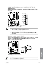
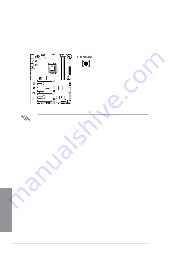
MemOK! button
Installing DIMMs that are not compatible with the motherboard may cause system
boot failure, and the DRAM_LED near the MemOK! button lights continuously. Press
and hold the MemOK! button until the DRAM_LED starts blinking to begin automatic
memory compatibility tuning for successful boot.
•
for the exact location of the DRAM_LED.
•
The DRAM_LED also lights up when the DIMM is not properly installed. Turn off the
system and reinstall the DIMM before using the MemOK! function.
•
The MemOK! button does not function under Windows
®
OS environment.
•
During the tuning process, the system loads and tests failsafe memory settings. It
takes about 30 seconds for the system to test one set of failsafe settings. If the test
fails, the system reboots and test the next set of failsafe settings. The blinking speed
of the DRAM_LED increases, indicating different test processes.
•
Due to memory tuning requirement, the system automatically reboots when each
timing set is tested. If the installed DIMMs still fail to boot after the whole tuning
process, the DRAM_LED lights continuously. Replace the DIMMs with ones
recommended in the Memory QVL (Qualified Vendors Lists) in this user manual or at
www.asus.com.
•
If you turn off the computer and replace DIMMs during the tuning process, the system
continues memory tuning after turning on the computer. To stop memory tuning, turn
off the computer and unplug the power cord for about 5–10 seconds.
•
If your system fails to boot up due to BIOS overclocking, press the MemOK! button
to boot and load the BIOS default settings. A message will appear during POST
reminding you that the BIOS has been restored to its default settings.
•
We recommend that you download and update to the latest BIOS version from
www.asus.com after using the MemOK! function.
Z97-WS
Z97-WS MemOK! button
Summary of Contents for Z97-WS
Page 1: ...Motherboard Z97 WS ...
Page 54: ...1 38 Chapter 1 Product introduction Chapter 1 ...
Page 59: ...Z97 WS 2 5 Chapter 2 To uninstall the CPU heatsink and fan assembly ...
Page 60: ...2 6 Chapter 2 Basic installation Chapter 2 To remove a DIMM 2 1 4 DIMM installation ...
Page 61: ...Z97 WS 2 7 Chapter 2 2 1 5 ATX Power connection OR ...
Page 62: ...2 8 Chapter 2 Basic installation Chapter 2 2 1 6 SATA device connection OR OR ...
Page 138: ...3 66 Chapter 3 BIOS setup Chapter 3 ...
Page 160: ...4 22 Chapter 4 Software support Chapter 4 ...
Page 180: ...6 12 Chapter 6 Multiple GPU support Chapter 6 ...
Page 186: ...A 6 Appendices Appendices ...


