Z97-WS
1-31
Chapter 1
DO NOT connect a 1394 cable to the USB connectors. Doing so will damage the
motherboard!
You can connect the front panel USB cable to the ASUS Q-Connector (USB) first, and then
install the Q-Connector (USB) to the USB connector onboard if your chassis supports front
panel USB ports.
The USB 2.0 module is purchased separately.
9.
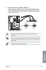
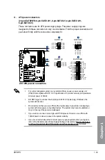
USB 2.0 connectors (10-1 pin USB1112, USB1314)
These connectors are for USB 2.0 ports. Connect the USB module cable to any of
these connectors, then install the module to a slot opening at the back of the system
chassis. These USB connectors comply with USB 2.0 specification that supports up to
48 Mb/s connection speed.
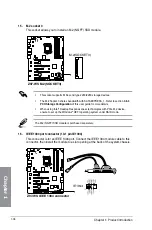
Z97-WS USB2.0 connectors
USB+5V USB_P12- GND NC
USB+5V
USB_P11-
GND
USB1112
PIN 1
USB+5V USB_P14- GND NC
USB+5V
USB_P13-
GND
USB1314
PIN 1
Z97-WS
Summary of Contents for Z97-WS
Page 1: ...Motherboard Z97 WS ...
Page 54: ...1 38 Chapter 1 Product introduction Chapter 1 ...
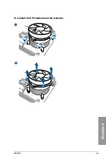
Page 59: ...Z97 WS 2 5 Chapter 2 To uninstall the CPU heatsink and fan assembly ...
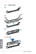
Page 60: ...2 6 Chapter 2 Basic installation Chapter 2 To remove a DIMM 2 1 4 DIMM installation ...
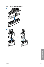
Page 61: ...Z97 WS 2 7 Chapter 2 2 1 5 ATX Power connection OR ...
Page 62: ...2 8 Chapter 2 Basic installation Chapter 2 2 1 6 SATA device connection OR OR ...
Page 138: ...3 66 Chapter 3 BIOS setup Chapter 3 ...
Page 160: ...4 22 Chapter 4 Software support Chapter 4 ...
Page 180: ...6 12 Chapter 6 Multiple GPU support Chapter 6 ...
Page 186: ...A 6 Appendices Appendices ...


