Z9PE-D16-10G Series
2-7
2.2.4
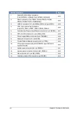
Layout contents
Jumpers
Page
1.
Clear RTC RAM (CLRTC1)
2-27
2.
VGA controller setting (3-pin VGA_SW1)
2-28
3.
LAN controller setting (3-pin LAN_SW1, LAN_SW2)
2-28
4.
PMBus 1.2 PSU select jumper (3-pin SMART_PSU1)
2-29
5.
ME firmware force recovery setting (3-pin ME_RCVR1)
2-29
6.
DDR3 thermal event setting (3-pin DIMMTRIP1)
2-30
7.
RAID configuration utility selection (3-pin RAID_SEL1)
2-30
8.
BMC Setting (3-pin BMC_EN1)
2-31
9.
Broadcom 10GbE controller setting (3 pin BMC10G_SW1)
2-31
Onboard LEDs
Page
1.
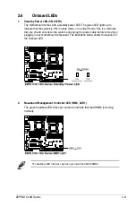
Standby Power LED (SB_PWR1)
2-21
2.
Baseboard Management Controller LED (BMC_LED1)
2-21
3.
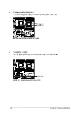
CPU Warning LED (ERR_CPU1)
2-22
4.
Power LED (+5V_LED1)
2-22
5.
Location LED (LOCLED1)
2-23
6.
DIMM warning LED
2-23
7.
CATT LED
2-24
8.
Q-Code LEDs
2-24
Slots/Sockets
Page
1.
CPU sockets
2-9
2.
DDR3 sockets
2-14
3.
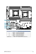
PCI Express x16 / PCI Express x8
2-18
4.
PIKE slot
2-18
Summary of Contents for Z9PE-D16-10G Series
Page 1: ...Motherboard Z9PE D16 10G Series ...
Page 14: ...xiv ...
Page 15: ...Chapter 1 Product Introduction ...
Page 21: ...Chapter 2 Hardware Information ...
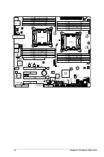
Page 25: ...Z9PE D16 10G Series 2 5 2 2 3 Motherboard layout ...
Page 26: ...2 6 Chapter 2 Hardware information ...
Page 64: ...2 44 Chapter 2 Hardware information ...
Page 65: ...Chapter 3 Powering Up ...
Page 69: ...Chapter 4 BIOS setup ...
Page 118: ...4 50 Chapter 4 BIOS setup ...
Page 119: ...Chapter 5 RAID Configuration ...
Page 157: ...Chapter 6 Driver installation ...
Page 193: ...Appendix A Reference Information ...
Page 195: ...Z9PE D16 10G Series A 3 A 1 Z9PE D16 10G Series block diagram ...
Page 196: ...A 4 Appendix A Reference information ...
Page 202: ......


