2-12
Chapter 2: Hardware information
K
J
8.
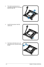
Push down the right load lever (J),
ensuring that the edge of the load plate is
fixed by the lever (K).
9.
Insert the right load lever under the
retention tab.
M
L
10. Push down the left load lever (L), and
then insert the lever under the retention
tab (M).
Summary of Contents for Z9PE-D16-10G Series
Page 1: ...Motherboard Z9PE D16 10G Series ...
Page 14: ...xiv ...
Page 15: ...Chapter 1 Product Introduction ...
Page 21: ...Chapter 2 Hardware Information ...
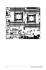
Page 25: ...Z9PE D16 10G Series 2 5 2 2 3 Motherboard layout ...
Page 26: ...2 6 Chapter 2 Hardware information ...
Page 64: ...2 44 Chapter 2 Hardware information ...
Page 65: ...Chapter 3 Powering Up ...
Page 69: ...Chapter 4 BIOS setup ...
Page 118: ...4 50 Chapter 4 BIOS setup ...
Page 119: ...Chapter 5 RAID Configuration ...
Page 157: ...Chapter 6 Driver installation ...
Page 193: ...Appendix A Reference Information ...
Page 195: ...Z9PE D16 10G Series A 3 A 1 Z9PE D16 10G Series block diagram ...
Page 196: ...A 4 Appendix A Reference information ...
Page 202: ......

