2-18
Chapter 2: Hardware information
* These IRQs are usually available for ISA or PCI devices.
IRQ
Priority Standard function
0
1
System Timer
1
2
Keyboard Controller
2
-
Programmable Interrupt
3*
11
Communications Port (COM2)
4*
12
Communications Port (COM1)
5*
13
--
6
14
Floppy Disk Controller
7*
15
--
8
3
System CMOS/Real Time Clock
9*
4
ACPI Mode when used
10*
5
IRQ Holder for PCI Steering
11*
6
IRQ Holder for PCI Steering
12*
7
PS/2 Compatible Mouse Port
13
8
Numeric Data Processor
14*
9
Primary IDE Channel
15*
10
Secondary IDE Channel
2.5.3
Interrupt assignments
Standard Interrupt assignments
2.5.4
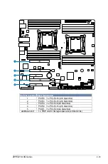
PCI Express x16 slot (x16 link)
The onboard PCIE 2 and PCIE4 provide two x16 Gen3 link to CPU2; The onboard PCIE 6
provide one x16 Gen3 link to CPU1. These slots support VGA cards and various server class
high performance add-on cards.
2.5.5
PCI Express x8 slot (x8 link)
The onboard PCIE 3 provides one x8 Gen3 link to CPU1.
2.5.6
PCI Express x8 slot (x4 link)
The onboard PCIE 1 provides one x4 Gen2 link to Intel PCH.
2.5.7
PIKE slots
The PIKE slot allows you to choose and change your preferred SAS solution easily. Install an
optional ASUS PIKE RAID card based on your needs.
Summary of Contents for Z9PE-D16-10G Series
Page 1: ...Motherboard Z9PE D16 10G Series ...
Page 14: ...xiv ...
Page 15: ...Chapter 1 Product Introduction ...
Page 21: ...Chapter 2 Hardware Information ...
Page 25: ...Z9PE D16 10G Series 2 5 2 2 3 Motherboard layout ...
Page 26: ...2 6 Chapter 2 Hardware information ...
Page 64: ...2 44 Chapter 2 Hardware information ...
Page 65: ...Chapter 3 Powering Up ...
Page 69: ...Chapter 4 BIOS setup ...
Page 118: ...4 50 Chapter 4 BIOS setup ...
Page 119: ...Chapter 5 RAID Configuration ...
Page 157: ...Chapter 6 Driver installation ...
Page 193: ...Appendix A Reference Information ...
Page 195: ...Z9PE D16 10G Series A 3 A 1 Z9PE D16 10G Series block diagram ...
Page 196: ...A 4 Appendix A Reference information ...
Page 202: ......


