background image


ASMV-160 

BETRIEBSANLEITUNG | OPERATING MANUAL


Technische Änderungen vorbehalten. Alle Angaben ohne Gewähr. Alle Rechte liegen bei der ASUTEC GmbH. 
Subject to technical modifications. No responsibility is accepted for the accuracy of this information. All rights are reserved by ASUTEC GmbH. 

Document nr. 85000061 – Version A – 2017/03/03   


WWW.ASUTEC.EU  

| 10

10

10

10


5.4 

MONTAGE INDUKTIVE SENSOREN 


5.4 

MOUNTING OF INDUCTIVE  


SENSORS 

Für die Montage der induktiven Sensoren 
werden Klemmhalter M16x1 in kurzer 
Ausführung verwendet.  
In diese Klemmhalter werden die Sensoren 
M12x1 bündig eingebaut. Verwenden Sie 
Sensoren mit 4 mm Bemessungsschaltabstand. 
Die Gewindebohrungen am Gerät sind im 
Anlieferungs-zustand mit Verschlussstopfen 
verschlossen. Für die Montage der Klemmhalter 
müssen diese Verschlusstopfen entfernt werden.


For mounting the inductive sensors, mounting 
clamps M16x1 in short version are used. 
In these mounting clamps the sensors can be 
flush mountend. Use sensors with a rated 
operating distance of 4 mm. 
The tapped holes on the device are sealed with 
the plug when delivered. For mounting the tool 
holder these sealing plugs must be removed. 


Die Klemmhalter für die obere (1) und für die 
abgesenkte Position (2) werden in den 
Befestigungsblock bis auf Anschlag 
eingeschraubt. Es besteht die Möglichkeit die 
Klemmhalter seitlich oder von vorne und hinten 
in den Befestigungsblock zu schrauben. 


The mounting clamps for the upper (1) and 
lower position (2) are screwed into the 
mounting block as far as they will go. There is 
the possibility to screw the clamping holders on 
the side or from the front and rear in the 
mounting block.


Um  die  eingefahrene  Stellung  des  Anschlags 
abzufragen, wird der Klemmhalter M16x1 in die 
dafür vorgesehene Bohrung geschraubt (3). 
Hierbei ist zu beachten, dass in diesem Fall keine 
mechanische  Begrenzung  vorhanden  ist,  die  die 
Einschraubtiefe des Klemmhalters vorgibt. 
Bei der Montage des Klemmhalters ist in diesem 
Fall folgedermaßen vorzugehen: 
-  schieben Sie den Anschlag in seine  
  eingefahrene Position. 
-  schrauben Sie den Klemmhalter soweit  
  hinein, bis er die Abfragestange berührt. 
-  Schrauben Sie den Klemmhalter etwa eine  
  Umdrehung zurück, um somit einen Schalt-
  abstand von ca. 1mm einzustellen. 
-  Kontern Sie den Klemmhalter mit einer  
  Mutter und montieren Sie den Sensor. 

In order to detect the retracted position of the 
stop, the mounting clamp M16x1 is screwed 
into the bore provided for this purpose (3). 
In this case, it should be noted that in this case 
there is no mechanical limitation which specifies 
the screw depth of the mounting clamp. 
When mounting the clamp, the following 
procedure should be followed: 
-  Slide the stop to its retracted position. 
-  Screw the mounting clamp in until it touches 
  the query shaft. 
-


Screw the mounting clamp back 

  approximately one revolution, in order to set 
  a switching distance of approx. 1 mm. 
-  Lock the clamp with a nut and mount the 
  sensor. 


5.5 

TAUSCH DER DÄMPFEINHEIT


5.5 

EXCHANGE OF DAMPING UNIT


Werkstückträger werden vom 
Verschiebeanschlag gedämpft und gestoppt.  
Die Dämpfung übernimmt eine hydraulische 
Dämpfeinheit. Je nach Belastung und 
Einsatzbedingungen ist bei Verschleiß die 
Dämpfeinheit zu tauschen.  
Die Austausch-Dämpfeinheit können Sie bei 
ASUTEC unter der Artikelbezeichnung  
„ASHD-160-11“ bestellen. 
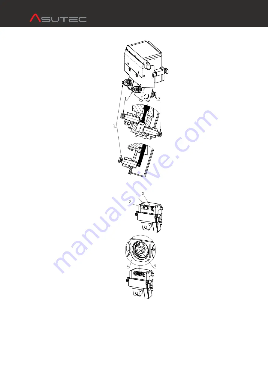
Bei dem Austausch der Dämpfeinheit gehen Sie 
folgendermaßen vor: 
-  lösen Sie die mittlere Schraube (1) und die 
   beiden äußeren Schrauben (2 und 3). 
-  entnehmen Sie den Anschlag und legen ihn  
  beiseite. 
-  demontieren Sie den Sicherungsring (4) 
-  Drehen Sie die Schraube (1) in die  
  Kolbenstange der Dämpfeinheit (5) und 
  ziehen Sie die Dämpfeinheit heraus. 
Die Montage der neuen Dämpfeinheit erfolgt 
analog der obigen Schritte, in umgekehrter 
Reihenfolge. Bitte beachten Sie, dass die mittlere 
Schraube (1) nach dem Anziehen noch Spiel hat. 
Dies ist beabsichtigt und hat die Funktion einer 
Kupplung.


Workpiece carriers are damped and stopped by 
the slide stop. A hydraulic damping unit is 
mounted in the device. Depending on load and 
operating conditions, the damping unit must be 
replaced when worn. 
The replacement damping unit can be ordered 
from ASUTEC with the article code  
"ASHD-160-11" 
When replacing the damping unit, proceed as 
follows: 
- Loosen the middle screw (1) and the two outer  
  screws (2 and 3). 
-  Remove the stop and set it aside. 
-  Disassemble the retaining ring (4) 
-  Turn the screw (1) into the piston rod of the 
  damping unit (5) and pull out the damping  
  unit. 
The assembly of the new steam unit takes place 
in the same way as the above steps, in reverse 
order. Please note that the center bolt (1) still 
has clearance after tightening. This is intended 
and has the function of a coupling. 


Summary of Contents for ASMV-160

Page 1: ... rights are reserved by ASUTEC GmbH Document nr 85000061 VersionA 2017 03 03 WWW ASUTEC EU 1 1 1 1 BETRIEBSANLEITUNG BETRIEBSANLEITUNG BETRIEBSANLEITUNG BETRIEBSANLEITUNG OPERATING MANUAL OPERATING MANUAL OPERATING MANUAL OPERATING MANUAL GERÄTETYP ASMV 160 DEVICE TYPE ASMV 160 GERÄTEBEZEICHNUNG Verschiebeanschlag mit Dämpfung pneumatisch DEVICE DESIGNATION Slide stop with damping pneumatically DO...

Page 2: ... structure of the warnings 2 1 2 Labeling of warnings 2 2 Safety regulations for personnel 2 3 Requirements for the installation location 2 4 Safety regulations for pneumatic components 2 5 Safety regulations for operating electronics 4 4 4 5 5 6 6 3 Technische Daten 3 1 Ausführung Gewicht 3 2 Arbeitsbereich 3 3 Vortriebskraft 3 4 Staudruck 3 5 Wirksame Kolbenflächen Kräfte 3 6 Funktion 3 7 Federk...

Page 3: ...schalter verwendet wird im Betrieb im direkten Kontakt mit verderblichen Gütern steht 1 3 IMPROPER USE FORESEEABLE MISUSE An improper use is when the slide stop is not used according to the above provisions is operated in vibration prone or potentially explosive atmospheres is used as a safety switch is in direct contact with perishable goods 1 4 HAFTUNG Grundsätzlich gelten unsere Lieferungs und ...

Page 4: ...ngen führen kann DANGER indicates a dangerous situation which if not avoided can lead to death or serious injury WARNUNG WARNING WARNUNG weist auf eine gefährliche Situation die wenn sie nicht vermieden wird zum Tod oder zu schweren Verletzungen führen kann WARNING indicates a dangerous situation which if not avoided can lead to death or serious injury VORSICHT ATTENTION VORSICHT bezeichnet eine g...

Page 5: ...rained and trained personnel The personnel must have experience in handling pneumatic and electrical systems The staff must be at least 18 years old and physically and mentally able to operate the ASUTEC device Personnel who are in general training or who are in instruction are only allowed to work on the ASUTEC device under the permanent supervision of an experienced person 2 3 VORAUSSETZUNGEN FÜ...

Page 6: ...ersonal mit elektrischer elektronischer Ausbildung darf an der elektrischen Ausrüstung arbeiten There is a risk of electric shock when working on electrical equipment that can result in serious injury or death Electrical equipment must comply with the relevant national safety regulations for the operating electrical system Only electricians with electrical electronic training are allowed to work o...

Page 7: ...ten Sie übernehmen somit die Transportsteuerung der Werkstückträger an einer Streckenkreuzung Der Verschiebeanschlag wird außen an das Streckenprofil zwischen die Umlenkung der Quertrecke montiert Verschiebeanschläge der Baureihe ASMV 160 können diese zwischen 2 parallele Längsstrecken mit den Abstandsmaß a montiert werden ausgenommen ASMV 160 DW 17 I 001 ASUTEC slide stops are made for stopping w...

Page 8: ...plate 4 9 cm Air consumption for retracting of the stop plate 3 8 cm 4 4 4 4 TRANSPORT TRANSPORT TRANSPORT TRANSPORT 4 4 4 4 TRANSPORT TRANSPORT TRANSPORT TRANSPORT VORSICHT ATTENTION Der Verschiebeanschlag wird von Hand transportiert Tragen Sie beim Transport Sicherheitsschuhe The slide stop is transported by hand Wear safety shoes during transport 5 5 5 5 MONTAGE MONTAGE MONTAGE MONTAGE 5 5 5 5 ...

Page 9: ...en Diese Zwischenplatte wird benötigt wenn der Verschiebeanschlag an ein 45 mm breites Streckenprofil zum Beispiel Rexroth ST 2 montiert wird Wird der Verschiebeanschlag an ein 50mm breites Streckenprofil zum Beispiel Rexroth ST 2 H montiert dann wird die Zwischenplatte nicht benötigt Für die Montage an Streckenprofil wird die Verwendung von Zentrierhülsen empfohlen Diese sind als Zubehör erhältli...

Page 10: ...ustellen Kontern Sie den Klemmhalter mit einer Mutter und montieren Sie den Sensor In order to detect the retracted position of the stop the mounting clamp M16x1 is screwed into the bore provided for this purpose 3 In this case it should be noted that in this case there is no mechanical limitation which specifies the screw depth of the mounting clamp When mounting the clamp the following procedure...

Page 11: ...n ohne Gewähr Alle Rechte liegen bei der ASUTEC GmbH Subject to technical modifications No responsibility is accepted for the accuracy of this information All rights are reserved by ASUTEC GmbH Document nr 85000061 VersionA 2017 03 03 WWW ASUTEC EU 11 11 11 11 5 6 ABMESSUNGEN 5 6 DIMENSIONS ...

Page 12: ...inheit ausgehoben kann den Verschiebeanschlag überfahren und den Quertransport fortsetzen The workpiece carrier is lifted up by the lift transverse unit can cross the slide stop and continue the movement in transverse direction Der Anschlag wird pneumatisch ausgefahren Das 5 3 Wegeventil siehe Kapitel 5 3 wird wieder in Mittelstellung geschaltet bevor der Werkstückträger gedämpft wird Der Werkstüc...

Page 13: ...in Danger by water in the electrics Only rub the components with a damp cloth Water must not flow or drip over the separator Water can penetrate into the electronic components Death by electric shock can be the result 7 2 WARTUNGSARBEITEN 7 2 MAINTENANCE WORK Das Gerät ist Wartungsfrei Reinigen Sie den Verschiebeanschlag und dessen Einsatzumgebung je nach Verschmutzungsgrad Der Bereich um den Ansc...

Page 14: ...SUTEC Nr Benennung Pos No ASUTEC No Description 1 14010004 Luftanschluss L Form M5 für Schlauch Außen Ø 6 mm 1 14010004 Push in L fitting Connection M5 for tubing O D 6 mm 2 14010006 Zuluftdrossel M5 für Schlauch Außen Ø 6 mm 2 14010006 Supply air one way flow valve Connection M5 for tubing O D 6mm 3 75000046 Befestigungssatz passend für die Montage des Verschiebeanschlags ASMV 160 mit und ohne Zw...

Page 15: ...wandte Normen DIN EN ISO 12100 Sicherheit von Maschinen allgemeine Gestaltungsleitsätze 2011 3 Die Inbetriebnahme dieser Maschine des Maschinenteils ist so lange untersagt bis festgestellt wurde dass die Maschine in die sie eingebaut werden soll den Bestimmungen den anwendbaren EG Richtlinien sowie den harmonisierten Normen Europanormen oder den entsprechenden nationalen Normen entspricht Köngen 0...

Reviews: