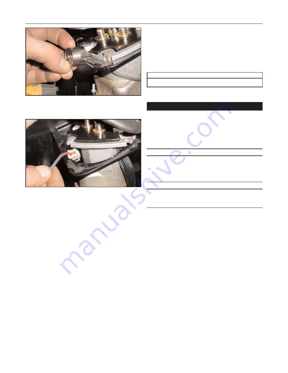
Figure 9-9 9-009
3.
Use an allen (hex) wrench to remove the bolt
securing the magnet to the joystick.
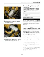
Figure 9-10 9-010
4.
Lift the joystick out of the mounting bracket slightly
to allow the magnet connector to pass between
them, then remove the magnet.
5.
To install the float magnet, reverse the removal
procedure.
Loader Valve Removal and
Installation
The tools required for loader valve removal and in-stal-
lation are listed in Table 9 3. Use manufacturer-recom-
mended tools whenever possible.
Table 9-3
Loader Valve Removal
Hot oil can cause personal injury. Lower all attach-
ments and make sure the oil is cool before remov-
ing any components or lines.
Remove the oil filler cap only when the engine is
stopped and the machine has been allowed to cool
thoroughly.
NOTICE
Collect and contain liquids in a suitable container.
Dispose of all liquids according to local regulations and
mandates.
Note:
During disassembly, cap all hoses and fittings to
prevent fluid loss and contamination of the system flu-
ids.
1.
Lower the lift arms to the ground.
2.
Turn the engine start switch to the OFF position.
3.
Relieve hydraulic pressure from the auxiliary cir
cuit.
4.
Drain the hydraulic fluid. Refer to Chapter 13.
Hydraulic Fluid and Filter Change.
9-4
Rubber Track Loader
9. Loader/Transmission Controls
Combination Wrenches
Required Tools
!WARNING!


