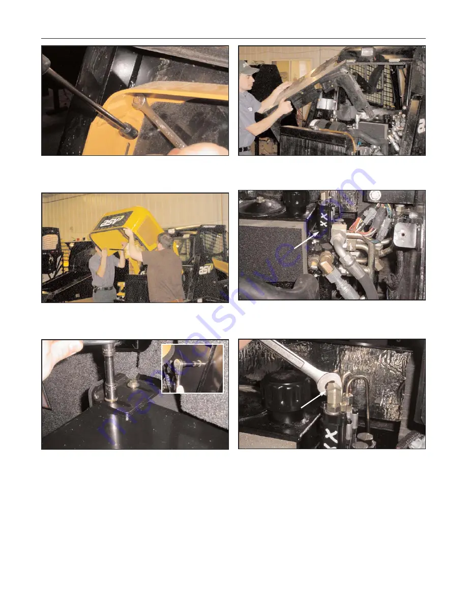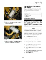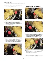
Figure 9-11 9-011
5.
Disconnect the gas springs, then remove the bolts
securing the hood as shown to allow for removal.
Figure 9-12 9-012
6.
Carefully remove the hood from the machine and
set it aside.
Figure 9-13 9-013
7.
Remove the bolts securing the rear valance panel
to the chassis to allow for removal.
Figure 9-14 9-014
8.
Carefully remove the rear valance from the
machine to allow access to the loader valve.
Figure 9-15 9-015
9.
Locate the loader valve on the side of the
hydraulic reservoir.
Figure 9-16 9-016
10.
Disconnect all of the tubes from the loader valve.
Cap and plug all openings to prevent fluid loss.
9-5
Rubber Track Loader
9. Loader/Transmission Controls
Loader Valve
Disconnect


