background image

Rubber Track Loader 

3. System Diagrams 

3-3 

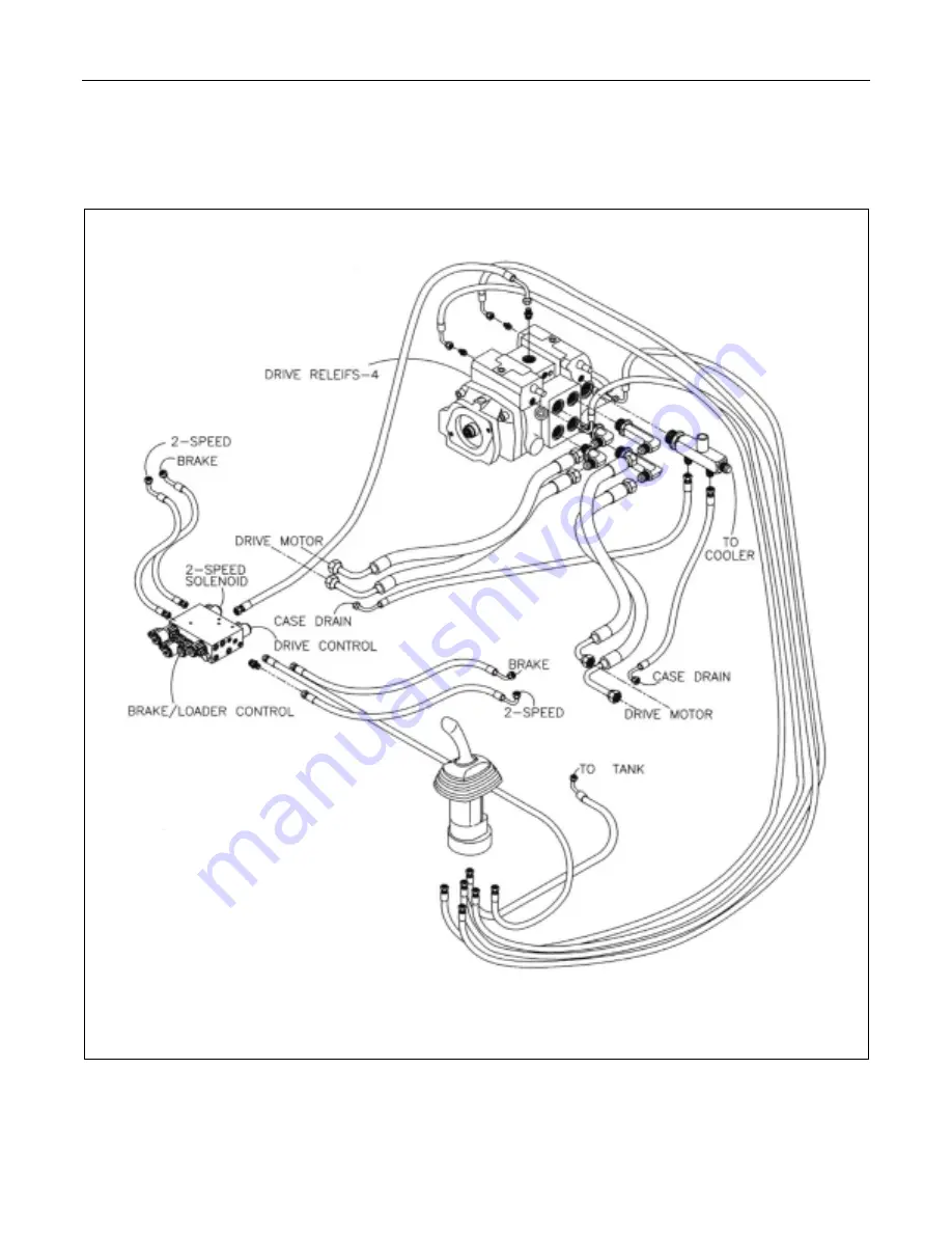
Drive Loop System  


Figure 3-3   RC-100 Drive Loop System 


Summary of Contents for RC-100

Page 1: ...ck Loader Safety Overview Technical Specifications System Diagrams Disassembly and Assembly Instructions Troubleshooting Maintenance Hydraulic Pressure Check Adjustment Service Manual ASVSP003 07 04 Part Number 0201 669 ...

Page 2: ......

Page 3: ...r Removal and Installation 5 1 Light Bar Removal 5 1 Ignition Switch Removal and Installation 5 2 Ignition Switch Removal 5 2 Ignition Switch Installation 5 3 Console Gauge Warning Panel Removal and Installation 5 4 Console Gauge Removal 5 4 Console Gauge Installation 5 4 Lap Bar Gas Assist Spring Removal and Installation 5 5 Lap Bar Gas Assist Spring Removal 5 5 Lap Bar Gas Assist Spring Installa...

Page 4: ...0 5 Drive Motor Removal 10 7 Wheel Removal 10 8 14 Wheel Keeper Plates 10 8 11 Maintenance Chapter Overview 11 1 Maintenance Schedule 11 1 Engine Oil 11 1 Oil Change Procedures 11 1 Engine Oil Specifications 11 1 Hydraulic Fluid and Filter 11 2 Hydraulic Fluid and Filter Change Procedures 11 2 Fuel Filter 11 3 Fuel Filter Change Procedures 11 3 Fuel Specifications 11 3 Air Cleaner 11 3 Air Filter ...

Page 5: ...uipment Note This label is used to provide important additional information comments explanations or amplification of the accompanying subject matter The person servicing the Rubber Track Loader may be unfamiliar with many of the systems on the ma chine This makes it important to use caution when performing service work Knowledge of the system and or components is important before the removal or d...

Page 6: ...electro lyte level Never disconnect any charging unit circuit or battery circuit cable from the battery when the charging unit is operating A spark can cause an explosion from the flammable vapor mixture of hy drogen and oxygen that is released from the electro lyte through the battery outlets Do not let electrolyte solution make contact with skin or eyes Electrolyte solution is an acid In case of...

Page 7: ...r to stop the engine 9 Be careful when removing cover plates Gradu ally back off the last two bolts or nuts located at opposite ends of the cover or device Then pry the cover loose to relieve any spring or other pressure before removing the last two nuts or bolts completely 10 Repairs requiring welding should be performed only with the benefit of the appropriate reference information and by person...

Page 8: ... as bestos Use a wet method to clean up asbestos debris A vacuum that is equipped with the high efficiency particulate air filter HEPA filter can also be used 2 Use exhaust ventilation on permanent machin ing jobs 3 Wear an approved respirator if there is no other way to control the dust 4 Comply with applicable rules and regulations for the work place In the USA use Occupational Safety and Health...

Page 9: ...Rubber Track Loader 1 Product Safety 1 5 Machine Label and Decal Examples Examples of the labels and decals placed on the machine are shown on this page ...

Page 10: ......

Page 11: ...andles Model CAT 4TH6 Auxiliary Pump Make Rexroth Type Axial Piston Variable Load Sense Displacement 3 844 in 3 rev 63 cc rev Max Flow 38 gpm 143 lpm 2300 rpm Relief pressure 3300 psi 22 752 kPa Marginal Pressure 362 psi 2 495 kPa Cooling filtering Oil is filtered and cooled at all times In auxiliary mode the oil is filtered af ter the attachment to protect the machine if the attachment motor fail...

Page 12: ......

Page 13: ...rams for the following RC 100 systems hydraulic charge system auxiliary cir cuit system drive loop system loader valve sole noid block and electrical attachment outlet Hydraulic Charge System Figure 3 1 RC 100 Hydraulic Charge System 15 LB RELIEF VALVE RETURN TO TANK ...

Page 14: ...Rubber Track Loader 3 System Diagrams 3 2 Auxiliary Circuit System Figure 3 2 RC 100 Auxiliary Circuit System ...

Page 15: ...Rubber Track Loader 3 System Diagrams 3 3 Drive Loop System Figure 3 3 RC 100 Drive Loop System ...

Page 16: ...Rubber Track Loader 3 Systems Diagrams 3 4 Loader Valve Figure 3 4 RC 100 Loader Valve ...

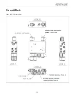
Page 17: ...Rubber Track Loader 3 Systems Diagrams 3 5 Solenoid Block Figure 3 5 RC 100 Solenoid Block POWER QUICK ATTACH OPERATOR PRESENCE LOADER FUNCTIONS OPERATOR PRESENCE DRIVE FUNCTION ...

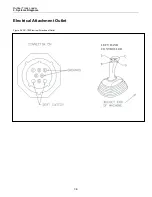
Page 18: ...Rubber Track Loader 3 Systems Diagrams 3 6 Electrical Attachment Outlet Figure 3 6 RC 100 Electrical Attachment Outlet LEFT HAND CONTROLLER ...

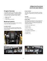
Page 19: ...ntrol 1 allows the operator to raise lower and pivot the attachment using a single pilot operated joystick Figure 4 1 Drive Control The drive control 2 allows the operator to change directions and speed using a simple pilot operated joystick Throttle The throttle controls engine rpm Dash Panel The dash panel Figures 4 2 4 3 is positioned for easy visibility in the heads up position inside the oper...

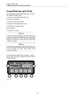
Page 20: ... engine coolant temperature engine oil pressure or hydraulic oil temperature lights illuminate during normal machine operation shut the machine down immediately Diagnose the problem and make needed repairs before continuing to operate NOTICE If the battery low voltage light illuminates drive the ma chine to a suitable location and shut the engine off Diag nose the problem and make needed repairs b...

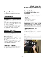
Page 21: ...Do Not Operate tag prominently on the ma chine to inform personnel that the machine is being worked on Before starting any disassembly or assembly proce dures refer to Chapter 2 Product Safety Repair for machine preparation information Preliminary Checkout If troubleshooting is required prior to disassembly or assembly refer to Chapter 13 Troubleshooting Operator Enclosure Disassembly and Assembly...

Page 22: ...rior components are now accessible for servicing Figure 5 4 4 View of light bar interior to operator s left when seated Figure 5 5 Ignition Switch Removal and Installation The tools required for ignition switch removal and installation are listed in Table 5 2 Use manufac turer recommended tools whenever possible Table 5 2 Required Tools Combination Wrench Ignition Switch Removal 1 Lower the light ...

Page 23: ...ll the ignition switch out from the rear of the dash panel Figure 5 8 4 Unplug the ignition switch connector Ignition Switch Installation Figure 5 9 1 Insert the ignition switch from the rear of the dash panel Figure 5 10 2 Install the nut that secures the ignition switch to the dash panel Figure 5 11 3 Plug in the ignition switch connector Remove Nut Install Nut ...

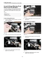
Page 24: ... Lower the light bar Refer to Chapter 5 Light Bar Removal procedure Remove Connectors Figure 5 12 2 Remove the connectors from the console gauge Remove Nuts Retaining Clip Figure 5 13 3 Remove the two nuts that secure the console gauge to the retaining clip Figure 5 14 4 Pull the console gauge out from the front of the dash panel Console Gauge Installation Figure 5 15 1 Insert the console gauge fr...

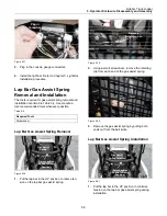
Page 25: ...ewdriver Lap Bar Gas Assist Spring Removal Raise Lap Bar Shown in Down Position Gas Assist Spring Figure 5 18 1 Put the lap bar in the UP position to relieve ten sion on the lap bar gas assist spring Remove Retaining Clip Figure 5 19 2 Using a small screwdriver remove the retaining clip from each end of the gas assist spring Figure 5 20 3 Remove the gas assist spring by pulling both ends out from ...

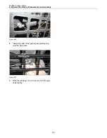
Page 26: ... Disassembly and Assembly 5 6 Install Endson Ball Joints Figure 5 22 2 Install the ends of the lap bar gas assist spring onto the ball joints Insert RetainingClip Figure 5 23 3 Slide the retaining clip on to each end of the gas assist spring ...

Page 27: ...embly proce dures refer to Chapter 2 Product Safety Repair for machine preparation information Preliminary Checkout If troubleshooting is required prior to disassembly or assembly refer to Chapter 13 Troubleshooting Disassembly and Assembly Procedures Disassembly and assembly procedures are provided for the following chassis components Fuel Sending Unit Cross over Tube Fuel Tanks Note Procedures a...

Page 28: ...he float mechanism when pulling it through the opening in the fuel tank Figure 6 3 Figure 6 4 Fuel Tank Removal The RC 100 has two fuel tanks that are connected by a cross over tube the procedure is basically the same for each tank 1 Drain the fuel tanks 2 With the engine cold remove the exhaust pipe and loosen the muffler The muffler does not need to be removed but having it loose will enable acc...

Page 29: ...re to fuel sending unit on right side tank 5 Remove fuel tank mounting bolts vent and return hoses on each tank use floor jack to secure fuel tanks Figure 6 8 6 Once a fuel tank has been removed the cross over tube can be removed from a hole on either side of the frame Remove Exhaust Pipe Cross over Tube Fitting Left Side Cross over Tube Fitting Right Side Remove Mounting bolts ...

Page 30: ......

Page 31: ...chine is being worked on Before starting any disassembly or assembly proce dures refer to Chapter 2 Product Safety Repair for machine preparation information Preliminary Checkout If troubleshooting is required prior to disassembly or assembly refer to Chapter 13 Troubleshooting Radiator Oil Cooler Disassembly and Assembly Procedures Disassembly and assembly procedures are provided for the followin...

Page 32: ...e sure there is proper clearance between the fan guard and the fan Air Conditioner Condenser Removal The tools required for radiator cooler removal and installations are listed below Use manufacturer recommended tools whenever possible Required Tools Combination Wrench Socket Wrench Figure 7 2 1 Remove the 4 bolts that secure the condenser to the fan shroud 2 Lift straight up while moving the cond...

Page 33: ...gure 7 7 Radiator Cooler Removal WARNING Hot oil can cause personal injury Make sure the oil is cool before removing any components or lines Remove the oil filler cap only when the engine is stopped and the filler cap is cool enough to touch with your bare hand WARNING Personal injury can result from hot coolant steam and alkali At operating temperature engine coolant is hot and under pressure The...

Page 34: ...uitable container Dispose of all liquids according to local regulations and mandates The tools required for radiator cooler removal and installations are listed below Use manufacturer recommended tools whenever possible Required Tools Combination Wrench Socket Wrench Screwdriver Hydraulic caps and plugs 1 Drain the hydraulic fluid Refer to Chapter 11 Hydraulic Fluid and Filter Change Figure 7 8 2 ...

Page 35: ... 7 12 6 Remove the lower radiator hose from the radia tor section Figure 7 13 7 Remove the two bottom hydraulic oil cooler hoses Cap and plug the fittings and hoses Figure 7 14 8 Remove the three bolts on each side of the Ra diator Cooler which fasten it to the frame Figure 7 15 9 Pull the radiator cooler straight up It may be necessary to move the fan shroud out of the way for the radiator cooler...

Page 36: ......

Page 37: ...ssembly or assembly proce dures refer to Chapter 2 Product Safety Repair for machine preparation information Preliminary Checkout If troubleshooting is required prior to disassembly or assembly refer to Chapter 13 Troubleshooting Loader Transmission Controls Disassembly and Assembly Procedures Disassembly and assembly procedures are provided for the following loader transmission control compo nent...

Page 38: ...before removing any components or lines Hot oil can cause personal injury 1 Lower the lift arms to the ground 2 Turn the engine switch to the OFF position and disconnect the battery 3 Remove the throttle linkage from the throttle handle Figure 8 1 Figure 8 2 Figure 8 3 4 Remove mounting screws from the plastic console Figure 8 4 Figure 8 5 ...

Page 39: ...and installations are listed in Table 8 1 Use manu facturer recommended tools whenever possible Table 8 1 Required Tools Screwdriver Open End Wrench Allen Wrench Loader Float Magnet Removal Pull the Boot Up Figure 8 8 7 Remove the rubber boot from the base of the joystick and pull the boot up Loader Float Magnet Figure 8 9 8 Locate the loader float magnet at the front of the control Remove Screw F...

Page 40: ...the control Install Screw Figure 8 13 2 The loader float magnet is held in place by an allen screw at the bottom of the magnet Install this screw Loader Float Magnet Figure 8 14 3 With the loader float magnet installed the con trol is ready to mount in the console 4 Position the control on the console and pull the rubber boot down over the base of the joystick 5 Re attach the plastic console ...

Page 41: ...Product Safety Repair for machine preparation information Preliminary Checkout If troubleshooting is required prior to disassembly or assembly refer to Chapter 13 Troubleshooting Hydrostatic and Hydraulic Pump Disassembly and As sembly Procedures Disassembly and assembly procedures are provided for the following transmission and drive components Charge Pump Auxiliary Piston Pump Tandem Pump Note P...

Page 42: ... lift arms to the ground 2 Turn the engine start switch to the OFF position 3 Relieve hydraulic pressure from the auxiliary circuit 4 Drain the hydraulic fluid Refer to Chapter 11 Hydraulic Fluid and Filter Change 5 Remove the Operators Manual compartment Figure 9 1 Figure 9 2 6 Remove the heel plate directly under the seat Figure 9 3 7 Remove the floor plate You will have to remove the plastic co...

Page 43: ... the 2 bolts that mount the pump to the auxiliary and remove the charge pump Figure 9 7 Auxiliary Pump Removal 1 Remove all hoses from auxiliary pump Figure 9 8 2 Loosen pump support bolt Pump support bolt has a jam nut on the engine end that should be loosen first Figure 9 9 3 Remove the two bolts that mount the auxiliary pump to the hydrostatic pumps Remove split flange Pump support bolt ...

Page 44: ...ollect and contain liquids in a suitable container Dispose of all liquids according to local regulations and mandates Note During disassembly cap all hoses and fittings to prevent fluid loss and contamination of the system fluids 1 Remove the charge pump and the auxiliary pump 2 Label and remove all the hoses and tubes from the tandem hydrostatic pump Be sure to cap all hoses and fittings Figure 9...

Page 45: ...ck washer and flat washer on the tandem pump at 85 ft lb with blue loctite Figure 9 14 Figure 9 15 2 Install the hoses and tubes on the tandem pump Hydraulic Reservoir Clean out If there has been a pump failure it is necessary to clean out the hydraulic reservoir as well has hoses tubes and hydraulic lines Figure 9 16 Figure 9 17 Pump shaft Install Bolt ...

Page 46: ......

Page 47: ... and tape the battery clamps and remove the key Place a Do Not Operate tag prominently on the machine to inform personnel that the machine is being worked on Before starting any disassembly or assembly procedures refer to Chapter 2 Product Safety Repair for machine preparation information Preliminary Checkout If troubleshooting is required prior to disassembly or assembly refer to Chapter 13 Troub...

Page 48: ... 3 2 Loosen lock bolt and release tension from the tension adjustment turnbuckle fig 10 3 Figure 10 4 2 Remove tensioning turnbuckle by removing front and rear nuts and bolts fig 10 4 3 Using a chain and chain binder pull the drive table forward until the hole in the front left corner lines up with the drive table pivot bracket fig 10 5 10 6 Figure 10 5 Figure 10 6 4 Insert a long bolt through the...

Page 49: ...need to be removed Figure 10 8 Figure 10 9 WARNING To remove the tracks the machine must be jacked up and placed on jack stands sturdy enough to support the weight of the machine The manufacturer approved jack stands are recommended Figure 10 10 1 Lubricate the front and rear 14 wheels with any good lubricant or a soap and water mixture fig 10 10 2 Using pry bars peel the tracks off of the front 1...

Page 50: ...haft keeper screws from the outside wheel plate 3 Install the track tool pivot base as shown in Figure 10 14 using the longer capscrews supplied with the pivot base Figure 10 14 Figure 10 15 3 Lubricate the front and rear 14 wheels 4 Get one end of the track partially on and then do the same thing to the other end the track tool works on both ends of the undercarriage Place the radius end of the t...

Page 51: ...y not need to be replaced at the same time as the roller Sprocket Removal and Installation The tools required for sprocket removal and installation are listed in Table 0 1 Use manufacturer recommended tools whenever possible Table 0 1 Required Tools Socket Wrench Combination Wrench Sprocket Removal 1 Remove the 7 bolts that fasten the bearing plate to the drive table Figure 10 18 Drive Sprocket Ro...

Page 52: ...off Figure 10 20 Figure 10 21 3 Remove the soft plug from the end of bearing flange and remove the snap ring on the shaft Figure 10 22 Figure 10 23 4 Using a puller remove the bearing and bearing housing from the shaft Figure 10 24 5 Remove the bolts that fasten that fasten the sprocket to the drive motor ...

Page 53: ...sembly 10 7 Figure 10 25 Figure 10 26 Drive Motor Removal 1 Drain the hydraulic fluid see chapter 11 Remove the bolts which fasten the drive motor to the drive table Figure 10 27 2 Remove all hoses from the drive motor Figure 10 28 Figure 10 29 Figure 10 30 ...

Page 54: ...ment 1 Remove the bolts which fasten the wheel tube to the frame rail there is two on the inside and 2 on the out side Figure 10 32 2 Remove the wheel shaft keeper plates from both ends of the shaft Figure 10 33 3 Unbolt the wheels from the tube and replace the center wheel is split for easy removal and installation Figure 10 34 Center wheel is split ...

Page 55: ... each for a total of 1 2 This can be done if the track has stretched to the point where the standard adjustment holes are not enough Figure 10 35 1 Flip both the inside and outside keeper plates on the end 14 wheels to increase the length The 14 wheel scrapers may need to be adjusted after this is performed Shown in the flipped position ...

Page 56: ......

Page 57: ...mary Air Filter Check daily clean and reuse as needed up to 5 times change at least once per year Secondary Air Filter Every 3 cleanings of primary filter Grease Fittings 8 hrs Posi Lube Lithium Grease Track Tension Break in and then as needed Coolant Test for coolant additive at 250 hrs Change at 1000 hrs or two years NOTICE When replacing engine coolant use Posi Lube Long Life 50 50 Antifreeze C...

Page 58: ...grade oil API CG 4 multigrade oil API CF 4 multigrade oil Hydraulic Fluid and Filter The hydraulic fluid should be changed every 500 service hours and the hydraulic filter should be changed every 250 hours Hydrostatic components require extremely clean oil for long service life Hydraulic Fluid and Filter Change Procedures WARNING Hot oil can cause personal injury Make sure the oil is cool before r...

Page 59: ...wist the drain counter clockwise to drain water from the bowl Figure 11 6 Fuel Filter The fuel filter should be changed every 500 service hours or as needed A plugged fuel filter can cause loss of engine power rough running or no start NOTICE Collect and contain liquids in a suitable container Dispose of all liquids according to local regulations and mandates Hydraulic Filters Case Drain Filter ch...

Page 60: ... air cleaner is one of the most important mainte nance items on the machine A poorly maintained air cleaner can seriously shorten the life of the engine Air Filter Change Procedures NOTICE When working in dusty conditions the air cleaner ele ments should be checked and changed more frequently than when working under normal conditions NOTICE Do not clean the primary air cleaner element by bumping a...

Page 61: ...hat fasten the drive table to the undercarriage frame rail Remove bolts if they are at the forward end of slots as shown in fig 11 11 Extend or retract tension turnbuckle if needed to take pressure off of the bolts 2 Extend the tension turnbuckle fig 11 12 until proper track tension is achieved Figure 11 11 Figure 11 12 3 Retighten or replace the two bolts on the drive table making sure the outsid...

Page 62: ...er wheel 3 Using a rope or wire put 90 pounds of down force on the track at the midpoint of the straight edge Figure 11 14 4 Using a ruler measure the distance between the straightedge and track The track should not de flect more than 1 inch or less than 0 75 inch be tween the top of the track and the straightedge 5 If the track deflects more than 1 inch tighten the track between 0 75 inch and 1 i...

Page 63: ... Preparation WARNING Accidental machine starting can cause injury or death to personnel working on the machine To avoid accidental machine starting disconnect the battery cables from the battery and tape the battery clamps and remove the key Place a Do Not Operate tag prominently on the ma chine to inform personnel that the machine is being worked on Before starting any disassembly or assembly pro...

Page 64: ... the pump as shown in figure 12 3 Auxiliary Pressure Check The service tools required for the auxiliary pressure check and adjustment are listed in Table 12 1 Use manufacturer recommended tools whenever possi ble Table 12 2 Required Tools Pressure Gauge Figure 12 4 1 Insert the hydraulic gauge into the test port on the bottom of the valve The test port has a plastic cover Figure 12 5 2 Dead head w...

Page 65: ...njury or death to personnel working on the machine To avoid accidental machine starting disconnect the battery cables from the battery and tape the battery clamps and remove the key Place a Do Not Operate tag prominently on the ma chine to inform personnel that the machine is being worked on Before starting any troubleshooting procedures re fer to Chapter 2 Product Safety Repair for ma chine prepa...

Page 66: ... adjusted to approximately 1 16 inch away from steel pickup bracket 4 Poor ground check ground wires on bottom left rear side of hydraulic reservoir 5 Safety relay is not activating 6 Faulty safety solenoid or safety solenoid spool 7 Poor wire connections on fuse relay or safety sole noid 8 Low charge pressure Problem 4 Lift arms operate but tracks will not move Probable cause 1 Leak in feed line ...

Page 67: ...tion 4 Loader valve malfunction Problem 11 Hot oil light illuminates hydraulic system operating hot Probable cause 1 Auxiliary hydraulic switch activated sending oil over relief 2 Low oil level 3 Debris plugging oil cooler limiting airflow 4 Debris plugging A C condenser limiting air flow 5 Broken fan blades 6 Loose fan belt 7 Improper attachment a Attachment must be rated machines flow capa bilit...

Page 68: ...Terex Construction Americas 8800 Rostin Road Southaven MS 38671 888 201 6008 662 393 1800 www terex com ...

Reviews: