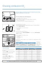
Checking combustion CO
2
The CO
2
percentage is set in the factory. This has to be checked during commissioning,
inspection, maintenance and in case of a failure.
CO
2
High Load reading
CO
2
Low Load reading
Finally, the CO
2
percentage at low load must
be checked:
• Press on the
DHW
- button until the minimum
value (0%) has been reached (low load)
This can be verified by means of the following action:
• Set the external controls to call for heat
• Make sure the boiler is operational and can get rid of the heat it produces
• Calibrate the flue gas analyser
• Place the lance of the flue gas analyser into the flue gas test point
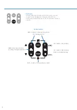
• Press both
+
buttons for 6 seconds
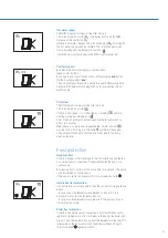
When the flame symbol and supply water temperature appears in the display the boiler
will be in
max heat output CH
.
• Press 1x the
eco
- button; the display shows:
1. Flow temp
2. Fan speed
• Press both
+
buttons again for 6 seconds;
The boiler will switch to
max heat output DHW
for iC range or again
max heat output
CH
for iS & iR range.
• Press 1x the
eco
- button; the display shows:
1. Flow temp
2. XX% (heat capacity)
3. Fan speed
Then with the
+ / -
button for DHW you can go to a different load, anything between full (100%)
and low load (0%)
°C
NOTE:
UNDER ALL CIRCUMSTANCES THE CO
2
AT LOW LOAD MUST BE LOWER THAN THE CO
2
AT FULL LOAD.
End of measuring:
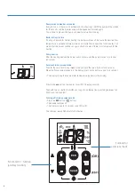
• Press the
ESC
button ( button).
The device switches off. The display shows
for 2 seconds code 180 or 181.
This complete the procedure.
FULL LOAD
NATURAL GAS (G20)
PROPANE GAS (G31)
CO
2
Nominal 9.0%
Nominal 10.3%
Minimum 8.6% – Maximum 9.6%
Minimum 9.9% – Maximum 11.0%
If required, you
may turn the
setting screw to
set the correct CO
2
percentage.
NATURAL GAS (G20)
LPG (G31)
Full load recorded
Accepted low load range
Full load recorded
Accepted low load range
9.6%
9.3% – 7.5%
11.0%
10.9% – 8.9%
9.5%
9.2% – 7.5%
10.9%
10.8% – 8.9%
9.4%
9.1% – 7.5%
10.8%
10.7% – 8.9%
9.3%
9.0% – 7.5%
10.7%
10.6% – 8.9%
9.2%
8.9% – 7.5%
10.6%
10.5% – 8.9%
9.1%
8.8% – 7.5%
10.5%
10.4% – 8.9%
9.0%
8.7% – 7.5%
10.4%
10.3% – 8.9%
8.9%
8.6% – 7.5%
10.3%
10.2% – 8.9%
8.8%
8.5% – 7.5%
10.2%
10.1% – 8.9%
8.7%
8.4% – 7.5%
10.1%
10.0% – 8.9%
8.6%
8.3% – 7.5%
10.0%
9.9% – 8.9%
9.9%
9.8% – 8.9%
°C
18
Summary of Contents for BC100124
Page 1: ...Appliance Technical Guide SERVICE ENGINEER EDITION ...
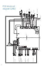
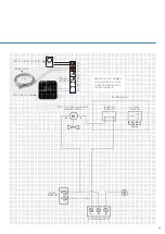
Page 24: ...PCB electrical diagram LMU 24 ...
Page 35: ...Notes 35 ...

