Installation & Servicing Instructions ATAG E-Series
26
Parameter chapter
PARA
Factory
Description
Range
1
85°C
maximum flow temperature CH
20 - 90°C
2*
01
type of CH installation:
radiators; air heating; convectors:
T max. flow 85°C; K factor heating line 2.3; gradient 5°C/min; gear differential 6°C
01
radiators with large surface areas or underfloor heating as additional heating:
T max. flow 70°C; K factor heating line 1.8; gradient 5°C/min; gear differential 5°C
02
under floor heating with radiators as additional heating:
T max. flow 60°C; K factor heating line 1.5; gradient 4°C/min; gear differential 4°C
03
full under floor heating:
T max. flow 50°C; K factor heating line 1.0; gradient 3°C/min; gear differential 3°C
04
3
max.
maximum power CH in kW
min-max
4*
00
control principal with on / off thermostat:
100 % on / off thermostat
00
100 % on / off weather dependant
01
5*
2.3
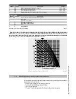
heating line K-factor (see also heating line graph)
0.2 - 3.5
6*
1.4
heating line exponent (see also heating line graph)
1.1 - 1.4
7*
-10
heating line climate zone (see also heating line graph)
-20 - 0
10*
0°C
fine adjustment heating line day temperature
-5 until 5°C
11*
0°C
fine adjustment heating line night temperature
-5 until 5°C
14
7
gradient speed
0 - 15
15*
0
booster after night reduction:
no
00
yes
01
23
-3°C
frost safety temperature
-20 until 10°C
31
63°C
switch-off temperature of additional cylinder with E boiler
40 - 80°C
36
0
type of three-way valve
VC 2010 / VC 8010 / VC 8610
00
VC 6940 modulating
01
43
max.
maximum power DHW in kW
min-max
45
0
Not applicable
00 - 01
89
00
address setting interface:
Spare
-01
ATAG Bus thermostat (BrainQ, Smart)
00
boiler 1 - 8 in cascade
00 - 07
Information chapter
INFO
Value
Description
1
°C
flow water temperature T1
4
°C
return water temperature T2
5
°C
DHW temperature T3
7
°C
outside temperature T4
8
°C
flue gas temperature T5
16
%
actual power in %
17
kW
actual power in kW
18
kW
actual load in kW
20
indication bus communication
21
GJ
consumption total in GJ (.. x 33 = .. m3)
22
GJ
consumption CH in GJ (.. x 33 = .. m3)
23
GJ
consumption DHW in GJ (.. x 33 = .. m3)
24
hour
total number of burner run hours
25
hour
number of burner run hours CH
26
hour
number of burner run hours DHW
32
hour
total number of hours counter
37
hour
total number of run hours pump CH and DHW
46
hour
within how many hours is service required
Summary of Contents for E 22C
Page 39: ...20 KIWA Certificate...


