4
V
ision
R
ecorder
C
HAPTER
2 I
NSTALLATION
T
his
chapter
explains
how
to
install
the
AT-VLT,
and
includes
the
following
topics
:
▲
P
ackage
C
ontents
–
L
ists
the
contents
of
the
AT-VLT
package
.
▲
I
nstallation
O
ptions
–
D
escribes
the
possible
ways
to
install
the
AT-VLT,
and
describes
how
to
attach
the
AT-VLT
to
a
wall
bracket
.
▲
C
onnections
–
D
escribes
the
mandatory
and
optional
cable
connections
,
including
instructions
on
how
to
start
the
AT-VLT.
▲
P
ower
–
D
escribes
the
AT-VLT
’s
power
requirements
and
backup
battery
operation
capability
,
and
explains
how
to
install
or
replace
batteries
.
P
ACKAGE
C
ONTENTS
T
he
AT-VLT
package
should
include
the
following
components
:
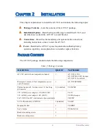
T
able
2: P
ackage
C
ontents
D
E
S
CRIP
T
ION
Q
U
AN
T
I
TY
P
AR
T
N
U
MBER
AT-VLT
unit
with
one
temperature
channel
1
AT-VLT (115V),
AT-VLT220 (220V E
urope
)
AT-VLT12 (
to
vehicle
)
W
aterproof
,
remote
33
feet
temperature
sensor
cord
(10
meters
)
1
AT-VLTSENSOR
T
hermal
paper
roll
, 2
inches
wide
, 131
feet
long
(40
meters
)
2 (1
installed
)
VLPAPER
12V AC/DC
power
adaptor
- US (120V) OR
12V AC/DC
power
adaptor
- EU (230V)
# AT-VLT12
has
DC
cord
instead
of
power
adaptor
1
VL115
VL220 (E
urope
)
CRCPW
3.6V L
ithium
battery
(CR2032)
1 (
installed
)
VLBAT
H
anging
bracket
1
VLBRKT
U
ser’s
G
uide
1
VLMANUAL
B
racket
mounting
screws
3
B
racket
securing
screw
1

